Download
1 / 30
310 likes | 329 Views
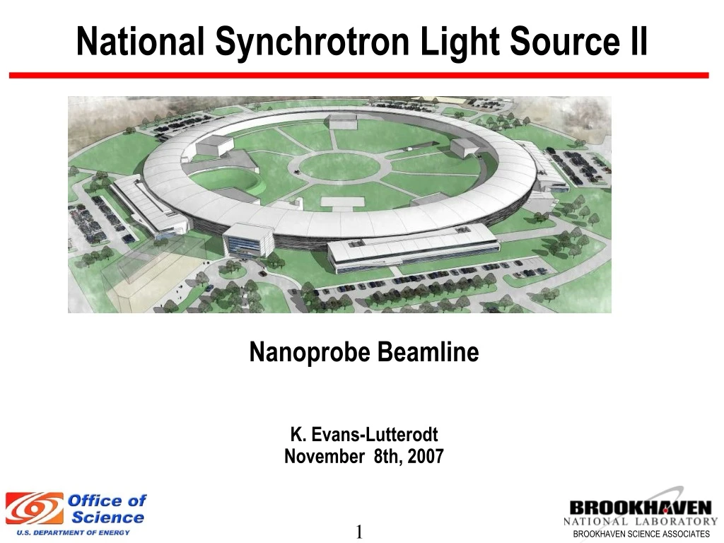
National Synchrotron Light Source II. Nanoprobe Beamline K. Evans-Lutterodt November 8th, 2007. Scientific Mission.

E N D
National Synchrotron Light Source II Nanoprobe Beamline K. Evans-Lutterodt November 8th, 2007
Scientific Mission Allow the study of nanomaterials which today play important roles in many diverse scientific fields, opening up a wide range of scientific problems ranging from studying the structure and function of catalytic nanoparticles, to the mapping of strain in buried grain boundaries, to determining the structure of single molecule devices.
Example: Energy Research Fully functioning micro-fuel cells Fritz Prinz, Stanford Univ. R. O’Hayre, F. B. Prinz, J. Electrochem. Soc. 151, A756 (2004) • Need to determine • Structure • Composition • Volume • Surface Area • of Pt nanoparticles in a carbon matrix
Beamline Requirements and Specifications • Requirements • 10% Source size stability • Floor vibration monitoring • 25nm floor noise; (active vibration isolation gives 0.25nm) • Remote endstation • Specifications • 1nm (convolution of spot size and mechanical stability) • Energy range*, 4.3 keV to 30 keV (covers elements Sc to U ) *Do not expect to have 1nm over entire energy range (18 keV+)
Physical Layout of Nanoprobe FOE Mono hutch 1 Mono hutch 2
Location XPCS Nanoprobe line
Insertion Device • CPMU U19, or U20 device • Low Beta straight section (maximum brightness)
Front end Layout • Front End Fixed Mask (FEFM) • Z=14m • Aperture Y=300um, X=1100um • Differential Pump • Z=14.5m • Front End Adjustable Horizontal Source Aperture (FEHA) • Z=16m • Aperture Y=open, X=(0-1500um)+/- 500um • Shield Wall • Z=26.7m
Engineering Analysis of Front End Fixed Mask Subjected to white beam from U19 CPMU device: Thermal Analysis Stress Distribution Analysis also performed for FE horizontal aperture
First Optics Enclosure • Contains: • Power filter (Diamond) • White beam Slits • Horizontal Focusing mirror • Conductance limiting Be window • High heat load mono • White beam monitor • Bremsstrahlung stop • Mono fluo screen • Secondary Horizontal Source Aperture (+ BPM) • Monochromatic shutter
Power management Undulator produces 7.8kW • FEFM (Mask) absorbs (7.8kW - 354W)=7.446 kW • HFM (Mirror) absorbs (354W-220W)= 134W • HHM (Mono) absorbs 220W • HRM ( Mono) ~0W
Monochromatic Hutch 1 Tertiary Slits Beam monitor High Resolution Mono
Monochromatic Hutches • Hutch 2 • 1 nm experimental endstation (at > 75m from source) • Includes nanofocusing optics and sample stage • Emphasizes fluorescent measurements Hutch 1 • Quad diode BPM • Aperture: Y=10mm, X=25mm • Removable • Tertiary Horizontal Source Aperture • Aperture Y=open, X = (0-5.0mm)+/-30mm • Monochromatic Fluorescent Screen • High-resolution mono (10-5 dE/E, removable fixed exit, energy range set by high res optics.) • Possible location for experimental endstation
Multilayer Laue Lenses • Deposit varied line-spacing grating on flat substrate (thinnest structures first) • Section to 5-20 m thickness (high aspect ratio structure) • Assemble two into a single device (MLL) Varied line-spacing grating substrate Depth-graded multilayers on flat Si substrate CNM, APS group: Maser et al. < 20nm performance!
Kinoform Optics Instead of solid refractive optic: Use a kinoform: K. E-L et al. (2003) • One can view the kinoform equivalently as • A blazed zone plate • An array of coherently interfering micro-lenses. < 80 nm
We do not need to re-design beamline to accommodate either optic • Beamline design issues are the same for types of optics: • Both are line focus elements: • will allow to correct for different vertical and horizontal source locations • Both are chromatic ~ 10-5, but MLL bandwidth is factor of 2 broader
Source Front End Aperture (FEFM + FEHA) Horizontal Focusing Mirror (HFM) Secondary Horizontal Source Aperture (SHSA) Focusing Optics Focal Point @ 76.01m . Operational Mode 1: Direct mode Endstation in mono hutch 2 ( back hutch) Side View
. Operational Mode 2: Waveguide mode Waveguide Secondary Focusing Optics Endstation in mono hutch 1 Primary Focusing Optics . . Source Focal Point @ 41.34m Secondary Horizontal Source Aperture (SHSA) Front End Aperture (FEFM + FEHA) Horizontal Focusing Mirror (HFM)
Endstation 1 (APS Nanoprobe/Xradia) Beam Direction Endstation Features First version being commisioned at APS Optical resolution 30nm Mechanical resolution projected 5nm More R&D required for positioning Fluorescence nanoprobe Full Field imaging Nano-Diffraction Nano-tomography Cryo sampleholder
Requirements imposed on Project On Conventional Facilities: • Real time monitoring of vibrations • Long beamline • Satellite Building • Utilities • Ramp over long beamline section On Accelerator Systems • Electron beam stability of 0.3 microns over 8 hrs
Outstanding Issues • Diamond filter thickness and phase error characterization • 1nm resolution optics; Ongoing R&D effort • Conservative mode is long beamline. • Progress elsewhere on waveguide mode might give shorter beamline • Vibration analysis/design ( see next)
Should we attach nanoprobe to ring or not? Option A: Nanoprobe slab connected to main ring Option B: Nanoprobe slab isolated from main ring Nick Simos; finite element analysis tools
And the answer is: and the system response Some vibration sources: Separating the nanoprobe remote slab reduces vibrations at experiment
Undulator Beamline 2 Hard X-ray Nanoprobe (HXN)Total Estimated Cost ($ x 1000) WBS Dictionary:All activity related to the design, construction, and commissioning without beam of an insertion device beamline for nanoprobe studies.
Summary • Nanoprobe line can be built to specifications, on time and on budget • The design will deliver 1nm beams and experimental capability that will have significant impact across a range of disciplines • Risks • Need significant improvements in positioning control • Optics R&D • Attention to vibration sources