Download

1 / 23
230 likes | 235 Views
MU-MIT. Chapter 03 Assemblers Nov 2007. Outline. This chapter is organized into four/five sections listed below. 3 Assemblers 3.1 General design procedure 3.2 Design of assembler Statement of problem Data structure Format of databases Algorithms Look for modularity

E N D
MU-MIT Chapter 03 Assemblers Nov 2007
Outline • This chapter is organized into four/five sections listed below. • 3 Assemblers • 3.1 General design procedure • 3.2 Design of assembler • Statement of problem • Data structure • Format of databases • Algorithms • Look for modularity • 3.3 Table processing • Sorting
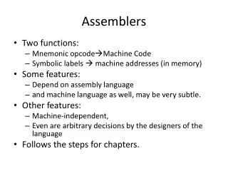
3 Assemblers • Assembler is system software which converts an assembly language program to its equivalent object code. • The input to the assembler is a source code written in assembly language (using mnemonics) and the output is an object code. • Basic Assembler functions: • Translatingmnemonic language to its equivalent object code. • Assigning machine addresses to symbolic labels. Fig: 3.1 Function of an assembler • Externally defined symbols are noted and passed on to the loader
3.1 General Design Procedure • In our design of an assembler, we are interested in producing machine language from a given assembly language. • Let’s start with the general problem of designing a software. We usually follow the following steps to design a software. • Specify the problem: specify all the requirements • Specify the data structure: (use set of tables) List out tables with fields (eg. Symbol table, opcode table, size of instruction ) • Define format of data structure:formats of database to be used • Specify algorithm: • Scan the program for labels-> first pass algorithm • Use for translation-> second pass algorithm • Look for modularity– divide program into smaller modules • Repeat 1 ~ 5 on modules These general software design procedure will be employed in our assembler design in this chapter……
3.2.1 Specify the Problem • Lets take the following assembly language program that we want to translate it to a machine code / object code. • Its immediate translation into machine code is available on the right side. Fig 3.2: An assembly program and its equivalent machine code
Purpose of Two Pass Assembler • Pass 1 – Define symbol and literals • Determine length of machine instructions (MOTGET1) • Keep track of location counter (LC) • Remember values of symbol until pass 2 (STSTO) • Process some pseudo-ops …EQU, DS • Remember literals (LITSTO) • Pass 2 – Generate object program • Look up value of symbols (STGET) • Generate Instructions (MOTGET2) • Generate data for DS, DC and literals • Process pseudo-ops (POTGET2) • Specifics of databases and detailed algorithm are discussed in next sections
3.2.2 Specify Data Structures Second step in our assembler design is establishing a data base that our assembler will work with. • Pass 1 Data Bases • Input source program • A location counter (keep track of instruction’s location) • A table, Machine Operation Table (MOT) • Indicates the symbolic mnemonic for each instruction and its length (2, 4 or 6 bytes) • A table, Pseudo-Operation Table (POT) • Indicate symbolic mnemonic and action to be taken for each pseudo-ops in Pass 1. • A table, Symbol Tables (ST) – store label and its value. • A table, Literal Table (LT)- literal and assigned location • Copy of input to be used in Pass 2- can be stored in Secondary storage.
Pass 2 Data bases • Copy of source program input to Pass 1. • Location Counter (LC) • A table, Machine Operation Table (MOT)- that indicates for each instruction: • Symbolic mnemonic, Length, Binary machine op-code & format(RS,RX, SI) • A table, Pseudo-Operation Table (POT)- that indicate for each pseudo-op the symbolic mnemonic and action to be taken in Pass 2. • A table, Symbol Tables (ST) – prepared by pass 1 containing each label and its corresponding value. • A table, Base Table (BT)- indicates which registers are currently specified as base register by USING pseudo-op and its contents. • A work space, INST, used to hold each instruction as its various parts (eg. Binary op-code, register fields, length fields, displacement fields) are being assembled together. • A work space, PRINT LINE, used to produce a printed listing • A work space, PUNCH CARD, used prior to actual outputting for converting the assembled instruction into a format suitable for loader.. • An output program in a format suitable for the loader
3.2.3 Format of Data Bases • The format of data bases section specifies the format and content of each data base- a task that needs to be undertaken even before describing the specific algorithm. • In reality Algorithm, Data bases, and Format are all interlocked. The designer has in mind some features of the format and algorithm when dealing with the data bases and iterate till all parts work. • Pass one requires a MOT with name and length where as pass 2 requires name, length, binary code and format. • We can use two tables with different format and contents or one table for both passes. • This is true for POT as well. We can also combine the POT and MOT into one table by generalizing the table formats. • In our example we will use same table for MOT and separate tables for POT.
Format …. Cont’d • Once we decide what information belong to each database, we can decide the format of the each entry. • Eg. In what format are symbols stored (left justified, padded with blanks, coded in EBCDIC or ASCCI) and what are the encoding conventions. • EBCDIC- Extended Binay Code Decimal Interchange Code is the standard 360 coding scheme. • Character A in EBCDIC is 1100 0001 or C1 in hex.
Format …. Cont’d • Pass 2 requires MOT and POT containing name, length, binary code and format • Pass 1 requires MOT and POT containing name and length • POT and MOT are fixed tables: their contents are not filled in or altered during the assembly process. • The op code is the key and its value is binary op code equivalent, which is stored for use in generating machine code • The instruction length is stored for use in updating the location counter. • The instruction format for use in forming equivalent machine code.
Fig 3.6: Possible content and format of MOT for passes 1 & 2
Fig 3.7: Possible content and format of POT for pass 1 (similar for pass 2)
Format ST and LT • Symbol and Literal Tables include not only name and assembly-time values but also length field and relative location counter. • The length field indicates the length in bytes of the instruction or data to which the symbol is attached. • Used by assembler to calculate length of an SS-type instruction. • Eg: COMMA DC C’,’ …. Has length 1 TEMP DS F …. Has length 4 Fig 3.8: Symbol table for passes 1 & 2: The relative location counter tells the assembler whether the value is relative or absolute. R for relative and A for absolute.
Format: Base Table • BT is used by the assembler to generate the proper base register reference in machine instruction and to compute the correct offset • The assembler must generate an address (offset, a base register number and index register number) for most symbolic references. • The ST contains the address of a symbol relative to the beginning of the program. Fig 3.9: Base table for pass 2
3.2.4 Algorithm • To show, a simplified algorithm for passes 1 & 2, illustrating most of the logical processes involved, two flow chart diagrams are used one for each pass. • Pass 1: Define Symbols • Assign location to each instruction and data defining pseudo-ops. • Define values for symbols appearing in the label field. • Initially LC set to first location in the program (relative address 0) • Then source statement is read examine op-code if it is pseudo-op if not, MOT is searched. • Matched entry specifies the length (2, 4 or 6 bytes) • Operand field is scanned for presence of Literals if found added to LT for later processing. • Label field is examined if there is a symbol added to ST along with the value of LC. • Finally LC incremented by length of current instruction and a copy is saved for pass 2. …repeat this for all instructions….
Pass 2: Generate Code • Once all symbols are defined (Pass 1) it is possible to finish the assembly by: • Determining value for operation code • Determine value for operand fields • Moreover, pass 2 structures generated code into a format suitable for a loader. • LC is initialized in the same fashion as pass 1 and processing continues as follows. • Instruction read from source file left by Pass 1. • Examine operation field to determine if it is pseudo-op if not search MOT and find the op-code. Matching entry specifies: Length, Binary op-code and Format of instruction • Operand fields of different instruction formats need different processing. • Finally a listing line containing copy of source code, hex value and location is printed… LC incremented and processing continues….