Download
1 / 11
110 likes | 274 Views
National Aeronautics and Space Administration Goddard Space Flight Center Greenbelt, MD. Radiometer Pre-Launch Calibration J. Piepmeier. Aquarius Science Algorithms Workshop March 21-22, 2007 NASA’s Goddard Space Flight Center.

E N D
National Aeronautics and Space Administration Goddard Space Flight Center Greenbelt, MD Radiometer Pre-Launch Calibration J. Piepmeier Aquarius Science Algorithms Workshop March 21-22, 2007 NASA’s Goddard Space Flight Center Information contained in this document may be subject to U.S. export control laws and regulations (22 C.F.R. 120-130 and 15 C.F.R. 730-774). To the extent that the information contained within is subject to U.S. export control laws and regulations, the recipient has the responsibility to obtain export licenses or other export authority as may be required before exporting such information to foreign countries or providing access to foreign nationals.
Outline • Radiometer Off-line Analysis System • Algorithm Theory – a couple of changes in works since CDR • Pre-Launch Calibration Testing – Cal Plan draft 2 in review • Radiometer Hardware Simulator – Matlab code written
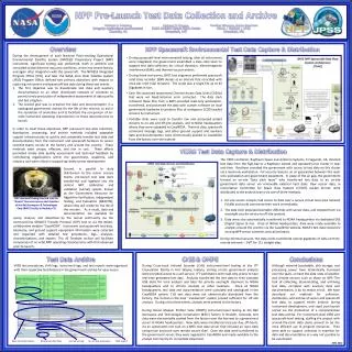
Radiometer Off-line Analysis System • EM Version • File based running on WAMP, MySQL and Matlab on WinXP64 • Input: Files of DPU packets with LabView timestamp and serial number from last ICDS hardware simulator reset. • Output files (all Matlab except first set) • Raw SA, LA, and (packed) HK DN’s – block based formatting • Unpacked SA, LA, and HK temps DN’s – frame based formatting • DN-to-EU converted HK temps and frame-averaged DN’s of SA and LA • Frame-averaged TA’s (v and h) in K w/out physical temperature dependence • FM Version • Same SW tools and I/O for now. Will update TA alg after I&T at GSFC • Input still file based • Output now stored in database storage indexed by timestamps
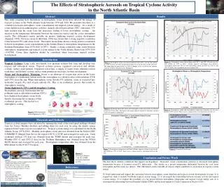
+ + S(ant) S(rad) T’’A Feedhorn Input Reference T’’Ao Feedhorn Output T’’Af OMT Output T’Af Antenna Feed SS Output T’A Radiometer SS Reference Plane Input TA RFE Input Ti Internal Calibration Plane Zone 1 Zone 2 Zone 3 Zone 4 Z-mismatch Zone 5 Zone 6 Switch + + L1,v T1 L2a T2a L2b T2b L3v T3v L4v T4v L5v T5v L6v T6v TCN,v Noise TCN,h TND,v Noise TND,h T0,v Ref Load Temp T0,h Trv Rad Noise Temp Trh TAA MOMT MCND Switch & coupler Feed Horn Thermal Isolator OMT loss +cables OMT Coupler Diplexer +cables Reflector + + L5h T5h L1,h T1 L2a T2a L2b T2b L3h T3h L4h T4h L6h T6h Radiometer Calibration Model Might move to here Need to update: L6 not separable from TND.
Current ATB Inverse model • Internal calibration at RFE • Loss corrections applied upstream to reflector • Polarimetric corrections depend on instrument performance
Alternate Inverse model • Pre-launch calibration of ND’s and DL’s referred to OMT-coupler inputs • Move Z-mismatch correction forward in model to between OMT-couplers and OMT • Loss corrections applied upstream from there to reflector [v,h,U] or [v,h,p,m] ---- (TAf’) X
Radiometer Hardware Simulator • What is it: Matlab code to mimic behavior of radiometer hardware • Purpose • Predict hardware behavior over temperature • Pre-run T/V calibration testing • Re-run tests in software for troubleshooting anomalies • Inputs • Hardware constants (gains, losses, phases, ENR’s, temp. coeff’s, etc.) • Thermal zone temperatures • Antenna temperature Stokes vector • Radiometer switch state (DL, ND, CND, blank) • Output • VFC frequency in kHz for four channels • Plans • Working with Susie to integrate in e2e simulator • Format data into DPU output stream • Feed data into GSFC I&T/Cal ground system
rad.OMTcouplers.L0=10.^([0 0]/10); rad.OMTcouplers.T0=296; rad.CND.dphi=0*pi/180; %phase imbalance in CND network rad.CND.L=[2 2]; %loss factors in cables and rat-race rad.CND.Fc=[20 20]; %coupling coefficients rad.CND.Fc_cT=[.001/30 .001/30]; %cT coupling coefficients rad.CND.TENR=(10^(23/10)-1)*295/10^(8/10); rad.CND.TENR_cT=.001; %cT TENR rad.CND.T0=296; %room temperature rad.diplexers.L0=10.^([0.3+.4 0.3+.4]/10); rad.diplexers.T0=296; %room temperature rad.Dicke.L0=10.^([0.1+.2 0.1+.2]/10);; rad.Dicke.T0=296; %room temperature rad.NDcouplers.L0=10.^([0.4 0.4]/10); rad.NDcouplers.T0=296; rad.ND.Fc=[20 20]; %coupling coefficients rad.ND.Fc_cT=[0 0]; %cT coupling coefficients rad.ND.TENR(1)=(10^(23/10)-1)*295/10^(11/10); %23 dB ENR, 11 dB atten rad.ND.TENR(2)=rad.ND.TENR(1); rad.ND.TENR_cT=[0 0]; %cT TENR rad.ND.T0=296; %room temperature rad.isolators.L0=10.^([0.4 0.4]/10); rad.isolators.T0=296; %room temp rad.LNA.G=10.^([30 30]/10); rad.LNA.G_cT=[-.002 -.002]; rad.LNA.Tlna=[50 50]; rad.LNA.T0=296; rad.BW=30e6; rad.RBE.G=10.^([45.4 45.4 45.4 45.4]/10); rad.RBE.G_cT=[-.002 -.002 -.002 -.002]; rad.RBE.T0=296; rad.DET.cD=[400 400 400 400]; rad.DET.cD_cT=[0 0 0 0]; rad.DET.T0=296; rad.VFC.G=[2000 2000 2000 2000]; rad.VFC.vinoff=[.05 .05 .05 .05]; %mV rad.VFC.vinoff_cT=[.0010 .0010 .0010 .0010]; %mV/C rad.VFC.voffset=[.35 .35 .35 .35]; %V rad.VFC.T0=296; rad.VFC.vfs=[10e3 10e3 10e3 10e3]; %mV rad.VFC.fmax=[100e3 100e3 100e3 100e3]; %Hz rad.VFC.sf= rad.VFC.fmax ./ rad.VFC.vfs ; %kHz/mV rad.tau = 8e-3; %seconds equiv integration time Radiometer Hardware Constants
Radiometer Timing Sequence Timing • 10-ms steps • 12 steps make 1 subcycle • 12 subcycles make one block Radiometer Sequencing • Antenna samples • 70 ms per sub-cycle • 3 x 10- and 2 x 20-ms bins • Internal calibration • 3-state asymmetric Dicke switching • 4-state sequence for polarimetric RFE calibration • Averaged over 10 samples/block • CND for polarimetric efficiency calibration once a subcycle • Null offset (blank) measured every block
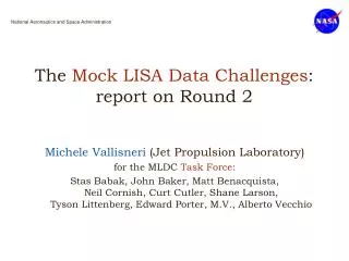
Instrument Block Diagram Radiometer Front End 1 (RFE1) Radiometer Digital Processing Unit (DPU) Radiometer Back End (RBE) Deployed Solid reflector Radiometer Subsystem (GSFC) Feed/OMT1 Diplexer 1H coupler CND 1V Diplexer coupler Chirp Generator Scatterometer Front End (SFE) Feed/OMT2 Scatterometer Back End (SBE) Feed/OMT3 SSPA Antenna Subsystem (JPL) LVPS Mechanical S/S & Thermal Control (JPL) Scatterometer Subsystem (JPL) Instrument Control and Data Subsystem (ICDS) (JPL) SAC-D Service Platform (S/P) (CONAE/INVAP) Pyros control Survival heaters Aquarius Power Distribution Unit (APDU) (JPL) RF cable Ctrl./telem Pwr distr.