Download
1 / 45
460 likes | 630 Views
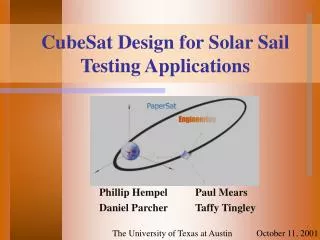
CubeSat Design for Solar Sail Testing Platform. Phillip Hempel Paul Mears Daniel Parcher Taffy Tingley. The University of Texas at Austin. December 5, 2001. Presentation Outline. Introduction. Tracking. Electronics. Structure & Deployment. Propulsion. Orbital Simulation. Budget.

E N D
CubeSat Design for Solar Sail Testing Platform Phillip Hempel Paul Mears Daniel Parcher Taffy Tingley The University of Texas at Austin December 5, 2001
Presentation Outline Introduction Tracking Electronics Structure & Deployment Propulsion Orbital Simulation Budget Conclusion
Project Goal • Design a Test Platform for Solar Sail Propulsion Technology • Measure thrust • Measure solar sail efficiency • Model satellite orbit
Constraints • CubeSat Prescribed Constraints • 10cm sided cube • 1 Kg weight • Timing system to delay power-on • Space-flown or approved materials • Adopted Constraints (for simplicity and reliability) • No attitude control • No powered systems (except required timer) • No communications systems
Laser Ranging • Information needed for thrust analysis • Orbital position for a significant portion of the satellite’s orbit • Rotation rates and angles over that time - A corner cube reflector (CCR) consists of three orthogonal mirrors that reflect light back to source
Laser Ranging • McDonald Observatory Laser Ranging (MLRS) • Satellite visibility sufficient • Can provide position to within 1 centimeter
Laser Ranging Specifics • Four CCR’s will define sail plane • Defines position and attitude • Double sided glass arrays with 3mm corner cubes (custom design) • Design impact • Volume and weight • Laser pulse force = 9.5e-26 N
Electronics • Rocket Data Acquisition System • Input - 10.7 V at 9-10 mA • Output- time coordinated voltages • Three UltraLife Lithium Ion Polymer Batteries • Output- 3.8V for 530 mAh • Thermal Analysis
Presentation Outline Introduction Tracking Electronics Structure & Deployment Propulsion Orbital Simulation Budget Conclusion
Mechanical SystemsPhillip Hempel Structural Design and Solar Sail Deployment
Satellite Components • Frame/ Corner Cube Reflectors • Satellite Components • Kill Switch • Timer • Sail • Capillaries • Inflation Capsule • Hardening Strips
Mechanical Overview • Satellite Components • Weight and Volume Budgets • Component Placement • Solar Sail Deployment / Model
Sequence of Events • CubeSat Released / Deactivate Kill Switch • Timer Waiting Period • Unlock Side Panels • Begin Inflation • Inflation Ends / Rigidization Occurs • Final shape
PropulsionTaffy Tingley Solar Sail Design and Finite Element Simulation
Solar Sail Material Aluminized Mylar
FE Test #1Direct Exposure – Neglect Coupled Thermal Stresses
FE Conclusions • Thermal Loading Not Worth Cost • Hardening Strip Corrections • All Deflections are Reasonable • FE Model Can Be Used for Future Analysis • Recommendation: Crack Propagation
Simulation Topics • Review: Four Body Problem with Thrust • Review: Initial Conditions • Rotating Thrust Vector • Umbra and Penumbra • Results: Orbits • Measuring Thrust with Observations and Simulations
Four Body Problem with Thrust • Physics Models: • Newton’s Law of Gravitation • Earth orbit perturbed by the Sun and the Moon • Solar Radiation Pressure • Generates thrust based on distance from Sun and sail attitude • Other Orbital Mechanics • Initial Conditions, Sun and Moon Position Vectors
Initial Conditions • CubeSat requires low altitudes due to cost • Perigee • LEO altitude • Highest velocity • Apogee • GEO altitude • Lowest velocity • Result: Highly eccentric orbit (e=0.74)
Rotating Thrust Vector • Thrust acts along the sail normal vector. • Sail normal is rotated in three dimensions.
Umbra and Penumbra • When the sail enters the Umbra, thrust is zero • Penumbra effects are ignored
Results: Thrust • Thrust Generated by Solar Radiation Pressure is:
Measuring Thrust • Purpose of simulation is to compare simulated orbit to observed orbit • Two possible situations: • Thrust accurately predicted by sail manufacturer. • Observed orbit equals simulated orbit • Thrust generated is different from prediction. • Comparison of simulated and observed orbits to determine thrust
Comparison Technique • Make several observations of position and attitude • Calculate orbit and sail rotation rate • Simulate orbit for known orbital elements and rotating sail normal • Extract thrust vector from equations of motion • Calculate the magnitude of the thrust vector
Presentation Outline Introduction Tracking Electronics Structure & Deployment Propulsion Orbital Simulation Budget Conclusion
Budget Summary • Personnel Costs 15,000 • Materials & Electronics 06,500 • Testing (CalPoly) 02,000 • Launch 50,000 • Total 73,500
Conclusion • PaperSat has developed a picosatellite design for the CubeSat program • Design will test solar sail propulsion technology • Design will not incorporate attitude control • Position, acceleration, and orientation will be measured from ground stations • Solar sail will be reflective on both sides with tear strips, hardening strips and inflation capillaries • Orbital simulation provides prediction of satellite orbit for thrust determination http://www.ae.utexas.edu/design/papersat/
Acknowledgements • Dr. Wallace Fowler • Dr. Cesar Ocampo • Dr. Eric Becker • Meredith Fitzpatrick • Previous CubeSat Design Groups