Download
1 / 11
110 likes | 221 Views
Improvair Ltd work alongside our clients to help specify and commercial kitchen air control systems. The canopies and kitchen heat exchanger supplied and fitted by our qualified installation team. Website: www.improvair.co.uk

E N D
Thermal Recovery Systems www.improvair.co.uk
Why are we here today? • To Develop a Working Relationship • Share information on a R & D basis In Return we offer • Carbon Reduction • Energy Savings • Cost Reduction
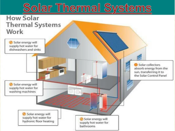
Principal Of Operation • The system comprises of a Bespoke Extract Canopy and Duct Heat Recovery System. • The patented system comprises of a Gas to Fluid (Air to water) heat exchanger. • Heat collected is transferred into a thermal Store. • This Energy is then used to pre-heat the cold mains supply water supply to feed dish washers, conventional hot water cylinder and / or combination boiler for heating or LPHW heater batteries.
Design of Heat Exchanger • The heat exchanger has been designed into the canopy and ductwork. • The heat is transferred in an inherently safe environment out side the contaminated air flow. • No heat exchangers within the canopy or ductwork – leaving no obstructions for inspection and cleaning. • No obstructions in the extract system – no effect on extract rates.
Explanation of Graph 1 • Graph number 1 S1 shows a temperature elevation of 19C over 6 hours from 20C to 39C. • S2 Shows the flow temperature from the canopy to the 300lt thermal store achieving 49C over the same duration. • These temperatures have been taken from only 24kw input from the test rig.
Explanation of Graph 2 • Here we ran 100lt of water off to waste every 30 minutes to simulate a working kitchen. • As you can see there was a steady rise in temperature during this process. • We collected 1.83kwh per hour with an input of 24kw LPG gas burner and copper sheet collection area of only 1.28m2 on the canopy and a duct collector area of 1.1m2