Download
1 / 11
110 likes | 246 Views
MICE CC Test Status. Ruben Carcagno 11/06/13. Cooldown. Completed week of September 9, 2013. SC Transition (voltages across each coil segment). Coil Temperature (calculated average in each of 8 coil segments). Problem. Cold mass surface temperatures steady but too high!

E N D
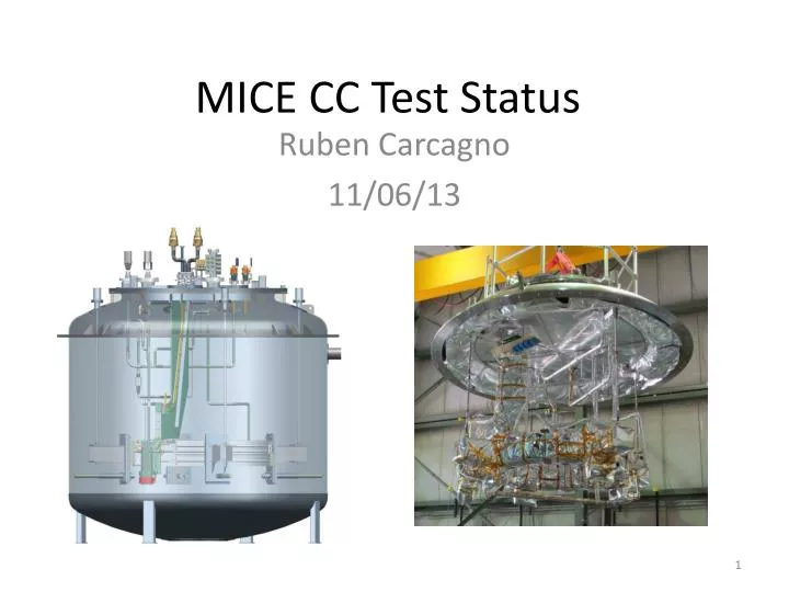
MICE CC Test Status Ruben Carcagno 11/06/13
Cooldown • Completed week of September 9, 2013 SC Transition (voltages across each coil segment) Coil Temperature (calculated average in each of 8 coil segments)
Problem • Cold mass surface temperatures steady but too high! • Cooling tube He temperature uniform ~4.6K • Test Stand cooling capacity adequate • Heat load to cold mass too high! • Large thermal gradients to cooling tube • Calculated ~ 10W, measured ~75W • Insulating vacuum was OK (10^-6 Torr), no measurable leaks
LBNL Thermal Model(Heng Pang) • Heat Load needs to be < 15 W for coil Tmax < 5.4 T (the critical temperature at 210 A) Tc at 210 A = 5.4 K
Comparison with Measurements • Measured cold mass surface temperatures correspond to a model uniform heat load between 40 and 80 W. Measured heat load was ~75W
Quench Performance • First “Quench” was a very fast (~ 1 ms) voltage spike at 62.8 A • Coil kept quenching at the same current with identical (slow) resistive growth – No training! • Lowering the cooling tube helium temperature by 350 mK to 4.26K increased the quench current by just 3 A, with identical resistive growth • Is the coil at the short sample limit? • Maybe, 7.63 K is extrapolated critical T at 62 A (See TD-12-009: Barzi & Turrioni) • Highest measured cold mass surface temperature was 7.49K, most temperatures between 6 to 6.5K • There could be a coil hot spot that we are not measuring
Findings • Decision was to start the warmup on 9/30/13, identify the source of extra heat load, fix it, and test again. • Inspection of the test cryostat and heat load calculations by various experts, including discussions with LBNL about their experience with the Spectrometer Solenoid, revealed no obvious single source of extra heat load but identified several issues associated with MLI installation. • Cold Mass MLI • Compressed MLI at some points, wrapping too tight in general • Possibility of trapped gasses in MLI blankets (no exposed edges, poor venting provisions), resulting in poor vacuum within the MLI blankets • MLI thermal shorts • Exposed cold sections of support rods • Vacuum vessel MLI • Thermally shorted by metal grommets used to support it (came already this way with the cryostat) • Possible high water vapor levels prior to cooldown • No Nitrogen pump and purge cycles
Solutions • Best solution would be to add a full coverage thermal shield to the test cryostat, but this solution is costly and long lead • Calculations show that if the cold mass MLI is installed properly, it should be adequate to keep the cold mass heat load below 15 W • The plan will focus in improving the MLI cold mass performance and providing some margin for installation errors by adding mechanical support thermal intercepts and increasing the number of layers
Plan • Re-wrap cold mass MLI • Spiral wrap cold mass with no more than 5 layers at a time to avoid thermal shorts • Increase the total number of layers from 40 to 60 • Loosely wrap MLI around cold mass and supports • Provide adequate venting (e.g. open edges, good communication to insulating vacuum, stitched taping, etc.) • Install MLI on cold sections of supports • Frequent inspection by subject matter experts during MLI installation • Vacuum vessel MLI • Consider applying an MLI blanket on top of the area thermally shorted by metal grommets near the vacuum vessel flange • Mechanical Supports Thermal Intercept • Loop the cold helium gas return pipe around the cold mass and use it to intercept heat from each of the four mechanical supports • Keep this pipe exposed inside the cold mass MLI, so it will function as a partial thermal shield above the cold mass • Insulating Vacuum Improvements • Relocate the 400 l/s turbo pump right next to the 6” pump out port. Turn off when energizing coil. • Install a Residual Gas Analyzer (RGA) and move vacuum instrumentation to a separate flange on the top plate • Conduct several cycles of Nitrogen pump and purge prior to cooldown, monitor water vapor levels with RGA • Add more temperature sensors for diagnostics • At the cold mass MLI surface and at a few elevations on the vacuum vessel MLI to determine MLI effectiveness • At the warmest cold mass spot predicted by the LBNL thermal mode (between the +lead and the –lead) • At a few points in the gas return pipe to estimate heat loads intercepted by this pipe
Status New thermal intercepts • Cold mass MLI has been removed • Detailed design on the thermal intercept and cold mass MLI wrapping is proceeding • Cost and schedule will be available once detailed design is complete • Expect to test again before end of the year • Trying to avoid complexity and long lead items • Trying to keep cost down • Work already started on relocation of turbo pump, instrumentation, etc. • Have obtained quotes from vendors (Meyer Tool, Aerospace Fabrication) for MLI installation and custom-cutting. • Expensive, long lead time • Recommend to proceed in-house New gas return pipe routing