Download
1 / 54
560 likes | 773 Views
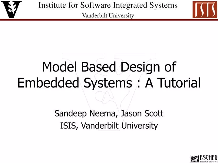
Model Based Design of Embedded Systems : A Tutorial. Sandeep Neema, Jason Scott ISIS, Vanderbilt University. ISIS Parameters. Established by the School of Engineering at Vanderbilt University in 1998 Academic/professional research organization

E N D
Model Based Design of Embedded Systems : A Tutorial Sandeep Neema, Jason Scott ISIS, Vanderbilt University
ISIS Parameters • Established by the School of Engineering at Vanderbilt University in 1998 • Academic/professional researchorganization • Composition (housed in 3 buildings): - 35 Research Scientists & Staff Engineers - 7 Faculty - 5 Admin Staff - 50 Graduate students • ~$11,000,000 in FY05 research awards • ~50 cost centers
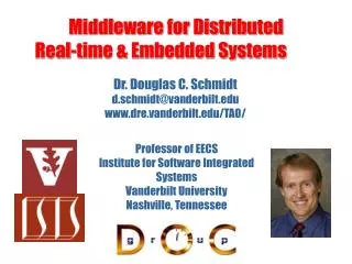
Research Thrusts • Model-Integrated Computing (MIC) • Modeling, model transformation, model analysis and code generation tools for MDA. Semantic foundations for embedded & hybrid systems. Open tool integration platform for MDA. • Middleware for Distributed Real-time & Embedded Systems • Adaptive & reflective middleware, model-based integration technology above component models, Real-time CORBA (ACE/TAO), Model Driven Architectures, secure middleware • Model-Based Systems Applications • Fault management, distributed control, automotive, avionics • Secure Networked Embedded System • Shooter location, security in system context
MIC Milestones 90’s Simulator Activity Modeling Tool - process models - activity models Process data Activity ModelingLanguage Diagnostics IPCS/DuPont FDIR Modeling Tool - physical - functional Diagnosability Analysis Tool Diagnostic System • Domain Specific Modeling Languages • Basic Model Translators • Composition platform: MGK • OODB 1990 • Developed: 1990-1993 • Deployed in 1993 • Used in Control Room DuPont Chemicals • Multiple aspect modeling • Metaprogrammable model builder: XGEM • Model migration XGEM • Developed: 1992-1994 • Deployed in 1995 • Used program wide 1995 DTool/Boeing International Space Station MIC Alliance • Metamodeling • Model-based distributed system integration • Multiple-target generators SSPF/SATURNMS Platform Data Servers Model-Based System Integration Tool Bottleneck Tool • Developed: 1995-1996 • Deployed in 1996 • Production use in 2 plants UML-basedMetamodeling Process Viewer GM-Saturn GME • Embeddable “Active” Models • Generative Modeling • GME x • Design space modeling Design space modeling Adaptive Target Rec. - Data Flow - Hardware Resources - Behavior Simulator 1999 EmbeddedModels SW Generator • Developed: 1997-2000 • HW/SW Co-design • VHDL generation VHDL Generator
MIC Milestones 00’s Applications Time Synch Services Coordination Services Lcaliza-tion Berkeley Motes/TINY-OS. • $ 50M DARPA Program created by Sztipanovits • Model Transformation Technology • Open Tool Integration Framework • Open Experimental Platforms 2000 GME 2000 OTIF DARPA GRATIS • $ 45M DARPA Program created by Sztipanovits • Fine-grain distributed system • Service composition • Exploration of new apps. (shooter location) DOC Group OMG MIC PSIG ESCHER Formed GReAT COSMIC DARPA Semantic Anchoring Pi-1 NSF • $ 13M Large ITR UC Berkeley/ISIS-VU • Hybrid Systems • Model-based design • Tool Architectures • Experimental Systems 2005 FSM ODE FCS Boeing Pi FM SYNL HY NSF TRUST System/Security Codesign ARCH Model-Based Design of Embedded Systems Pi+1 NSF-ITR CON IMP • MIC Applications: • Network-centric systems • Security-systems co-design in embedded systems • Systems biology • Automotive, avionics, unmanned systems applications • MIC Infrastructure: • Semantic anchoring of DSML-s (embedded systems) • Model transformations • Model synthesis • Active models • Metaprogrammable tool designs Future NSF TRUST S&TC DARPA, DoD Industry Funding
ESCHER • Embedded Systems Consortium for Hybrid and Embedded Research • Structure • Founded in 2003 as a 501(c)(3) Non-profit Research Institute • Management Team, Board of Directors, Industrial Advisory Board • Initial Funding • Industry: Raytheon, Boeing, General Motors • Government: Defense Advanced Research Projects Agency, National Science Foundation
ESCHERMission and Services MISSION Conduct activities as a non-profit corporation that enable the transition of government-funded information technology research results to industry and government customers SERVICES Research Activities – Identification and management of R&D projects via consortia, pooled funding, and multiple performers Repository Operation – Management of a quality controlled repository of software, tools, and documentation Technology Roadmapping – Forecasting the direction of new technologies, products, and research needs for Government and industry • Emphasis on embedded computing technology research and development • Long-term • Pre-competitive
ESCHER Impact Government and Military • Bridge the gap between research results and product development • Provide persistence until acquisition programs are ready Industry • Provide access to transition-ready results in a manageable format • Leverage pooled funding for a “multiplier effect” that allows significant Returns on Investment • Perform technical and programmatic management of complex performer arrangements Research Community • Allow performers to build on existing results • Increase the opportunity for research teams to “mature” government-funded technology • Provide a transition path for research into systems and products
Why Model-based Design • Complexity • Scale, Size, Functionality, Heterogeneity • Resource Limitation • Functionality demands always exceed the resource availability • Embedding concerns • Embedded software realizes a physical system (x-by-wire, navigation controllers, …) • Must obey the laws of physical interactions • Analyzability and Verifiability • Long development times, requires assurance on performance and functionality before implementation • … • Abstractions • Hallmark of all engineering disciplines • Critical to manage and solve large complex design problems • “constraining” an unbounded design-space • Abstractions Design Problem : Impedance (mis)match • Semantic gap between the problem space and solution space • Domain Specific Abstractions
Outline • Model-Integrated Computing • The MIC Tool Suite • Signal Processing Toolchain - An MIC Application • Heterogeneous Dataflow Programming Model • Demo • SPP Tool Chain SW Radio Demodulation • Summary
Outline • Model-Integrated Computing • The MIC Tool Suite • Signal Processing Toolchain - An MIC Application • Heterogeneous Dataflow Programming Model • Demo • SPP Tool Chain SW Radio Demodulation • Summary
A Model-based Development Process Analysis Feedback on design Tool Modeling Tools Multi-aspect Domain-Specific Models Multi-aspect Domain-Specific Models Multi-aspect Domain-Specific Models Generation Generator Custom code Build process Execution Monitoring Application Feedback from system Software Platform Hardware Platform MIC focuses on the formal representation, composition, and manipulation of models throughout the system lifecycle.
Core Issues in MIC • Modeling • Model Data Management • Model Transformation • Tool Integration
Domain Specific Modeling Languages L = < C, A, S, MS, MC> Abstract Syntax A Concrete Syntax C Parsing MC Concepts Relations Well formed-nessrules Notation forrepresenting models SemanticMapping MS Semantic DomainS Mathematical abstraction for specifying the meaning of models Domain Specific Modeling Language (DSML) • Model: precise representation of artifacts in a modeling language L • Modeling language: defined by the notation (C), concepts/relations and integrity constraints (A), the semantic domain (S) and mapping among these. • Metamodel: formal (i.e. precise) representation of the modeling language L using a metamodeling language LM.
Modeling Tool: GME Decorator Decorator XML XML XML XML XML DB #n DB #1 GME Architecture • Configuration through UML and OCL-based metamodels • Extensible architecture through COM • Multiple standard backend support (ODBC, XML) • Multiple language support: C++, VB, Python, Java, C# COM COM GME Editor ConstraintManager Browser Add-On(s) Translator(s) COM Metamodel GModel GMeta XML UML / OCL CORE Paradigm Definition CM XML ODBC … … Storage Options VSS/ ClearCase
Model Data Management • To have a conceptual view of data/models that is independent of the persistence format. • Such a conceptual view should be based on standards such as UML. • Have uniform access to data/models such that persistence formats can be changed seamlessly at either design time or run time. • Generate a domain specific API to access a particular class of data/models.
Model Transformation DSML1DM DSML2DM Physical interface Physical interface S C C S Transformation T DSML-1 DSML-2 Rewrite Engine MC2 MC1 MS2 MS1 A A MDSML1,DSML2 Input Models Target Models Input abstract syntax Output abstract syntax MOFADSML1 MTLTDSML1,DSM2 MOFADSML2 MOF MOF UMT M12: MOFADSML1MOFADSML2 Input Interface API API Output Interface GReAT UDM Metamodel of Transformation Meta-level: Translator design Metamodel of Input Metamodel of Output Implementation: Execution • Relevant Use of Model Transformations: • Building integrated models by extracting information from separate model databases • Generating models for simulation and analysis tools • Defining semantics for DSML-s • MIC Model transformation technology: • Must be formal and verifiable • Based on graph transformations • Model transformations are specified using metamodels and the code is automatically generated from the rewriting rules.
Model Transformation Tool: GReAT C/G GRE GME DEBUG Tools: UMT Language, GRE (engine), C/G, GR-DEBUG
Open Tool Integration Framework • Share models using Publish/Subscribe Metaphor • Status: • Completed, tested in several tool chains • Protocols in OMG/CORBA • CORBA as a transport layer • Integration with ECLIPSE is in progress Karsai, ISIS-Vanderbilt RFP is Discussed at MIC PSIG OMG http://www.isis.vanderbilt.edu/Projects/WOTIF/default.html
The MIC Tool Suite OTIF Component Abstraction (TA) Design Space Modeling (MD) Design Space Encoding (TE) Component Reconstruction Design Decoding Design Space Pruning Generic Model Editor GME Unified Data Model Design Space Exploration UDM • Best of Breed • Modeling Tools • Simulators • Verifiers • Model Checkers DESERT Meta Models Open Tool IntegrationFramework GReAT Model Transformation ESCHER Quality Controlled Repository: http://repo.isis.vanderbilt.edu
The MIC Development Process Metamodeling Tool Integration Analysis Metamodels Domain models Translation Domain-specific modeling Synthesis & Generation Model-Model Transformations Execution • Systems are constructed from domain-specific models • Analysis and generation are core activities • Development starts with domain engineering • Understand and capture domain concepts and variabilities • Develop Domain-Specific Modeling Language(s) that capture • Domain concepts as first-class objects • Domain variabilities as attributes and composition • Domain-Specific Tools play a key role in the development process • Modeling environment(s) for DSML-s • Model transformation tools • Model analysis tools • Model-based generators
Outline • Model-Integrated Computing • The MIC Tool Suite • Signal Processing Toolchain - An MIC Application • Heterogeneous Dataflow Programming Model • Demo • SPP Tool Chain SW Radio Demodulation • Summary
Signal Processing Tool Chain • Goals: • Design and synthesis of heterogeneous, distributed, embedded signal processing applications • Resource Constrained Hardware Platforms • Novel architectures • System-on-Chip, Cell, Embedded Processor • Heterogeneous processing resources • FPGA, DSP, RISC, … • Dynamic reconfiguration • Product Family Support • Single algorithm/application • Diverse target platforms • Approach: • Model-based Design Tools • Domain-Specific Modeling Language • Design Space Exploration • Model Transformations for Synthesis and Analysis • Asynchronous, Heterogeneous, Dataflow Programming Model • Light-weight, Portable, Asynchronous Dataflow execution Runtime
Signal Processing Tool Chain SPML/GME System Design Space Optimization Tools DESERT Design space exploration S2D D2S Analysis Tools MATLAB Functional Validation Signal Flow Modeling SPML/GME Point-Design Configuration Simulink/ Stateflow S2A AIRES Schedulability Ptolemy S2C CO-Active Execution Platform Libraries VHDL CONF Comm Interf Target HW
Dataflow Programming Model P2 P3 P6 P1 P4 P5 R1 R2 R3 {P,F,A} P – set of dataflow components F P P – set of dataflow A: P R – resource assignment • Dataflow Variants • Synchronous, Asynchronous, Dynamic Dataflow, … • Well-suited for multi-rate signal processing types of applications • Not so well suited for reactive applications • Hierarchy and Design Space • Syntactic extensions for managing complexity • Heterogeneous dataflow • Component implementation agnostic
Signal Processing Modeling Language • SPML is an integrated DSML incorporating multiple sub-languages • Component Modeling • Typed and Type Polymorphic • SW Architecture Modeling • Design Space Modeling • Generative Modeling • HW Architecture Modeling • System Configuration Modeling • Analyses • Type Compatibility • Type Dependency Analysis • Redundancy Detection and Elimination • Functional Analysis • Timing Analysis
Component-Based Design • Components are data-driven and communicate asynchronously • Processing tasks triggered by availability of data • Works well for complex, heterogeneous systems • Allows for algorithm data dependencies to be explicitly defined straightforward to map onto concurrent hardware • Alternative implementations may be specified (“Alternative” construct) • Example: Correlation may be implemented in time or freq domain • The SPP tool supports system design with the following categories of components: • Software Components (c, c++) • Hardware Components (vhdl) • Matlab Components (*.m) Asynchronous Communication Buffer Worker Function Comm Comm Software Hardware FIFO Hardware Queue in kernel Software Process Hardware Component Stream Stream FIFO FIFO
Algorithm Hardware Algorithm • Asynchronous dataflow execution semantics • Components (processes) of dataflow can be in hw or sw Sig1 Preproc FFT BPF IFFT XCorr Disp IFFT Sig2 Preproc FFT BPF • Heterogeneous resources • Communication via point-to-point links • Different physical protocol over different links • TI comm • FPGA-FPGA • FPGA-AD Target Platform A/D FPGA DSP PowerPC TI Comm Port Ethernet TI Comm Port DSP PC
Partitioning/Mapping Dataflow A/D FPGA DSP PC Sig1 Preproc FFT BPF IFFT XCorr Disp IFFT Sig2 Preproc FFT BPF
Interface Insertion FPGA DSP Preproc FFT BPF IFFT Protocol Driver Physical Channel Protocol Driver XCorr Mux Demux IFFT Preproc FFT BPF • Each physical channel is assigned an interface based on the system model • Synthesis tools select from a library of Interfaces • Interfaces are chosen based on: • Communicating hardware types • Physical communication protocol • Number of streams across a physical channel • Data type • Process flow control (HW)
Runtime Environment • Abstraction of architectural details • Implements common execution semantics (asynchronous dataflow) across heterogeneous targets (software/hardware) • Low overhead/high performance • Target-able for synthesis from interpreters • Extensible to new hardware • Software: Kernel implements async dataflow semantics • Non-preemptive scheduler executes dataflow processes in a round-robin fashion • Communication API for inter-process communication enabling asynchronous data-exchange • between two processes on the same processor • between two processes on different devices • Hardware: Components implement async dataflow semantics • Component topology automatically synthesized by tools • Parallelism is explicit
Radio Transmitter Geo-location • Goal: Find arrival times of transmitted signal at various receivers • Need phase-accurate recovered baseband signal from receivers • Bypass of analog FM demod a necessity! • FM demod for low-SNR situations • Online FM demodulation needed for continuous listening • Size, power, weight constrained embedded platform T2 T5 T4 T1 T3 450 KHz IF (goes to A/D) Frequency Synthesizer LNA T6 Antenna 20MHz Sharp IF Filter 465MHz High-”Q” Filter Hyperbolic curve of location Quad Demod and Mixer Compander Audio AMP and speaker output
FM Demodulation IF input from Rx IF Filter Hilbert FM Demod H(t) tan-1 d dθ e-jθ Quadrature FM Demod Shift to Baseband Input: FM modulated signal, IF=450kHz Recovered Baseband signal Input: FM modulated signal (Intermediate Frequency – 450kHz) Output: recovered baseband signal GME: Introduce application
SPP Software Components • API provided for inter-component communication: void C_HilbertFir(long *local, long cmd) { FLOAT_BLK *in, *real_out, *imag_out; int buf_size; if( ((in1 = (FLOAT_BLK *)get_input_buffer(0)) != 0) && output_slot_available(0) && output_slot_available(1) ) { buf_size = sizeof(FLOAT_BLK)/sizeof(long); real_out = (FLOAT_BLK *)get_buffer(buf_size); imag_out = (FLOAT_BLK *)get_buffer(buf_size); dequeue(0); hilbert_fir_filter(in1->data, in1->vector_len, real_out->data, imag_out->data); enqueue_output(0,real_out); enqueue_output(1,imag_out); } return; } GME: WALK THROUGH SW COMPONENT
SPP Hardware Components • Component coding standard defined for I/O: ENTITY IfFilter11Tap is port ( InputPort_0 : in std_logic_vector(31 downto 0); InputPort_0_DVALID : in std_logic; InputPort_0_DCLR : out std_logic; OutputPort : out std_logic_vector(31 downto 0); OutputPort_DVALID : out std_logic; OutputPort_DCLR : in std_logic; reset : in std_logic; clk : in std_logic ); end IfFilter11Tap; ARCHITECTURE arch_IfFilter11Tap of IfFilter11Tap IS COMPONENT fir_11tap_ser port ( ND: IN std_logic; RDY: OUT std_logic; CLK: IN std_logic; RST: IN std_logic; RFD: OUT std_logic; DIN: IN std_logic_VECTOR(15 downto 0); DOUT: OUT std_logic_VECTOR(15 downto 0) ); END COMPONENT; … … FirFilter_11tap_ser fir_11tap_ser Clk Reset GME: WALK THROUGH HW COMPONENT
Hardware Process Flow Control N+2 connections N Data Data Available Data Ack Clk Clk Reset Reset Parallel data transfer 3 connections Serial Data Strobe Ready Clk Clk Reset Reset Serial data transfer
SPP Matlab Components • API provided for inter-component communication function new_local = ML_FirFilter(local, cmd) if( m_output_slot_available(1) & m_input_slot_available(1) ) in = m_get_input_buffer(1); m_dequeue(1); out = if_fir_filter(in); m_dequeue(1); m_enqueue_output(1, out); end new_local = local; GME: WALK THROUGH MATLAB COMPONENT
Platform Model • Composed of processing elements • Processing elements communication via channels GME: WALK THROUGH PLATFORM MODEL
Supported Platforms Communication Mechanisms: • TCP/Ethernet • TCP/Ethernet • TI comm ports • TI comm ports, OPB bus ifc, custom defined • MEX ifc Currently supported platforms: • PC • PowerPC (Other general purpose processors can usually be supported with little effort) • TI TMS320C6711 DSP • Field Programmable Gate Arrays (FPGAs) Xilinx (V2Pro, V4 w/embedded PPC cores), Altera • “Matlab”
DEMO: Build SW Radio Model • Build-up Matlab/PC application • Demo hw/sw/ml model application
Runtime Framework Virtex 4 FPGA PowerPC Hard Core(s) PC Processor FM Playback Tan-1 Forwarder d/dθ Matlab Fix 2 Float Mix_Down Ethernet Splitter Time Plot OPB Bus Spec Plot SPP Peripheral Interface HILBERT FIR FILT IF FIR FILTER
Signal Processing Tool Chain SPML/GME System Design Space Optimization Tools DESERT Design space exploration S2D D2S Analysis Tools MATLAB Functional Validation Signal Flow Modeling SPML/GME Point-Design Configuration Simulink/ Stateflow S2A AIRES Schedulability Ptolemy S2C CO-Active Execution Platform VHDL for hw components HW interface components to SW SW interface components to HW Insertion of splitters, forwarders, type conversion Libraries VHDL CONF Comm Interf - Real-time Schedules - SW communication maps - Config files for vendor tools: *.dsw VC++ project files *.wpj files for VxWorks/Tornado *.pao,*.bdd component declarations for Xilinx EDK tools FPGA Synthesis C/C++ Compilers Target HW
SPP Tool Chain • Signal Processing Modeling Language (SPML/GME) • GME based domain-specific modeling environment that allows representation of: • Application dataflow • hierarchical network of application components (C/C++/ML code modules, VHDL soft macros, hard macros), and alternatives • Heterogeneous execution platform • hierarchical network of resources (FPGA-s, PowerPC-s, RISC-s, DSP-s) • Design Space Exploration Tool (DESERT) • Assist in making design decision based on user-defined constraints • Prunes the design-space eliminating design configurations that do not satisfy constraints • Runtime Execution Platform (CoActive) • Macro dataflow execution kernel, supporting communication across heterogeneous resources, providing location-transparency to components • Simulation/Analysis Tools (Matlab, AIRES)
Key SPML Modeling Concepts • Design Space Modeling • Hierarchical dataflow w/ alternatives • Type Polymorphic Component Modeling • Typed ports, type/size relations between ports • Matlab/C/C++/HDL implementation • Platform-independent Core modeling • Allows synthesis of platform-specific wrappers
Generative Modeling • Compact/Scalable representation of repetitive structures • Replication groups defined by connecting ports and models with a replicator object • Replication Plug-in elaborates models with replicator constructs Before Replication Group After
Type-Checking • OCL constraints for checking type compatibility between connected ports • Constraint-checker offers advanced debugging support for detecting constraint failure location
Auto-Type Assignment • Component Type Models allow assigning multiple types for ports - supporting type-polymorphism within models • Component Type Models contains type relations between ports as • Identical || Tuples [(ta,tx),(tb,ty),…] • A single type must be selected in component instances for SA configuration synthesis • Plug-in automatically assigns types based on type-relations and user-inputs
Auto-Size Assignment • Component ports have attributes for size of data-packets • Component types allow modeling of size relations between component ports • arithmetic expressions over $dst and $src • Plug-in automatically assigns sizes for component instances based on size-relations and user-inputs
Platform-Specific Wrapper Synthesis • Model platform-independent computational cores • Model their integration within platform components • Synthesize platform wrapper code • SA wrapper • MEX wrapper • CoActive wrapper • Benefits: rapid development of platform component library using off-the-shelf SP libraries ex. Siglib, VSIP, …