Download
1 / 58
580 likes | 587 Views
This research study investigates the importance of cleanliness testing for printed wiring boards. It discusses new flux designs and methods for predicting solvent action. The findings demonstrate the significance of ionic cleanliness for product reliability.

E N D
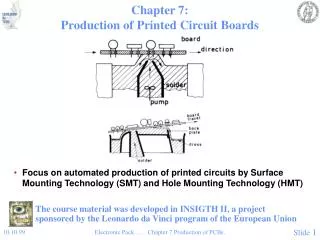
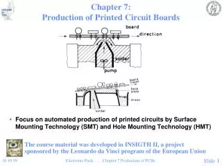
Ionic Cleanliness Testing Research of Printed Wiring Boards For Purposes of Process Control Dr. Mike Bixenman, Kyzen Corporation Dr. Ning Chen Lee, Indium Corporation Steve Stach, Austin American Technology SMTAI
Agenda • Background • Why is Cleanliness Testing Important? • New Fluxes Designs • Predicting Solvent Action • Hypotheses • Methodology • Data Findings • Accept / Reject Hypotheses • Inferences from the Data
Ionic Cleanliness Testing • In use since the sixties • Ionic contaminants dissolved in the extract solution • Solubility of residue needed to measure ionic levels Source: http://www.scscoatings.com/parylene_equipment/omegameter.aspx
Cleanliness Testing Importance • Product reliability is directly relative to ionic cleanliness
Assessing Cleanliness Today • Non-destructive testing often fails to detect … • Advanced flux designs • Residues under capacitors, resistors, and array components
R.O.S.E. Testing • Production Floor Ionic Cleanliness Standard for 37 years • IPA75% / H2O25% extract solution
Moore’s Law Source: http://en.wikipedia.org/wiki/File:Transistor_Count_and_Moore%27s_Law_-_2008.svg
No-Clean Soldering • Disruptive technology empowered by Ozone Depletion • Goal was to eliminate in-production cleaning Source: http://en.wikipedia.org/wiki/Ozone_depletion
Miniaturization • Most obvious electronics industry trend • Moore’s law serving as the engine • Feature size reduction • Mechanical hole pitch and via reduction • Component reduction • Drives multiple changes in flux technology
New Flux Designs • Miniaturization Drives Change • Flux Consistency • Oxide • Oxygen Penetration Path • Flux Burn Off • Wetting Speed • Spattering • Soldering Under Air • Lead Free • High Temperature • Poor Wetting • Large Dendrite Source: Lee, 2009
Flux Consistency • Solder power shifting from • Type 3 ~ 25 to 45 microns • Type 4 ~ 20 to 37 microns • Flux requires changes for printing and soldering yields • More homogenous • Increased viscosity ~ Thixotrophic • Assembly process is more vulnerable to • Bridging ~ requires more slump resistance Source: http://www.indium.com/blogs/Solar-Blog/No-Slump-Metallization-Paste/20080730,38,2862/
Oxide Formation • Volume reduction • Alloy and Flux • Reduced in proportion to decreasing pitch • Solder materials shrink in proportion to pitch • Thickness of metal oxide does not shrink in proportion to pitch • Amount of oxide to re removed by unit volume of flux • Increases with decreasing pad dimension • Capacity per unit amount of flux needs to be increased
Oxygen Penetration Path • While pitch and pad size decrease • Oxygen penetration path through flux and alloy also decrease • Results in rapid oxidation of • Flux materials ~ increased cleaning difficulty • Increased levels of flux • Flux with greater oxidation resistance and barrier needed
Flux Burn Off • Vaporization of solvent carriers in flux • Increases with increasing exposure area per unit volume • Flux burn off increases with decreasing flux quantity deposited • Flux employed for finer pitch needs to be • More non-volatile • High molecular weight materials needed • Changes solubility parameter • More resistance to burn off
Wetting Speed • Fast wetting can cause problems during reflow soldering • Defects due to unbalance wetting force • Tombstoning • Swimming • Increase with decreasing component size • Sensitivity toward miniaturization • Fluxes with slower wetting speed allow • More time for the wetting force to be balanced • Decreases defect rate Source: http://www.xs4all.nl/~tersted/PDF_files/Plexus/tombstoning.pdf
Spattering • Caused by moisture pick-up in solder paste • Miniaturization brings • Solder joint closer to gold fingers • Increased vulnerability toward solder spattering • Fast solder coalescence action increases the problem • To minimize spattering • Fluxes with low moisture pickup and wetting speed are needed
Soldering Under Air • Miniaturization causes • More oxides • Easier oxygen penetration • Soldering in air increases the change in • Flux compositions • Desired flux should provide • Oxidation resistance • Oxygen barrier to protect parts during reflow Source: http://www.circuitmart.com/pdf/nitrogen_effect_for_wave_soldering.pdf
Lead Free • Main stream alloys • High tin compositions • Surface finishes • OSP • HASL • Immersion Ag, ENIG, and Sn • Complexities include • High Temperature • Poor Wetting • Large Dendrite
Lead Free High Temperature • High tin alloy melting range • 217-227C • Soldering temp usually 20-40C higher than eutectic SnPb • Higher temperature causes • Increased thermal flux decomposition • More flux burn off • Oxidation of fluxes and metals • To avoid problems caused by high temperature soldering • Flux require higher thermal stability • Higher resistance to burn off • Higher oxidation resistance • Higher oxygen barrier
Poorer Wetting • Surface tension of lead free alloys • SAC ~ 0.55-0.57 N/m • 20% higher than SnPb ~ 0.51N/m • Results in poorer alloy • Wetting • Spreading • Deficiencies are compensated by new fluxes • Lower surface tension to improve solder spread • Higher flux capacity ~ higher flux strength
Large Dendrite Formation • Does not normally cause early failures • Tin crystalline lattice and unfavorable grain orientation • Poses reliability concern • Reliability concern can be alleviated by • Forming solder joint with refined grain structure • Improved flux compositions
R.O.S.E. Problems • Test method relies on dissolving flux residue • Many of the new flux compositions do no dissolve • Ionic contaminants in flux not detected
Hypotheses H1: The extract solution (IPA75% /H2O25%) will not adequately dissolve many of today’s flux technologies H2: A new test solvent that dissolves all flux technologies is needed
Predicting Solvent Action • Hildebrand (1936) • Solubility of a solvent’s ability to dissolve a contaminant • Proportional to cohesive energy of the solvent • Solvent molecules overcome soils with similar solvency behavior • Hansen (1966) • Hildebrand’s Theory broken into 3 – parts • Dispersion Force • Polar Force • Hydrogen Bonding Force
Source: Hydrogen Bonding, 2009, Wikipedia Components of Hansen Space • Dispersive Force • Predominates for non-polar soils • Polar Force • Differences in electronic dipole differences • Positive and negative electron forces attract • Hydrogen Bonding • Ability to exchange electrons
Methodology • 9 Flux Residue compositions evaluated • Rosin ~ 1 • No-Clean designed for Tin-Lead ~ 5 • No-Clean designed for Lead-Free ~ 1 • Water Soluble designed for Tin-Lead ~ 1 • Water Soluble designed for Lead-Free ~ 1 • 20 Solvents with known HSPs • Flux residues exposed for 1-hour to 20 Solvents • Solubility Graded for each Solvent • Data placed into HSPiP Software • HSP for flux residue calculated
Relative Energy Difference • Ra ~ Given solvent and its reference value • Ro ~ Interaction radius of the sphere RED = Ra/Ro • 0 = No energy difference – Easily Dissolved • <1 = Inside Solvents – High Affinity • Close to 1 – Boundary Condition – Disperses Soil • > 1 = Outside Solvents – Low Affinity
Accept or Reject Research Hypotheses? H1 - IPA 75% / H2O will not dissolve today’s flux residues Second set of tests were run
Kinetics vs. Thermodynamics • Thermodynamics • Solvency parameters for dissolving the soil • Kinetics • Thermal – temperature affects • Impingement – energy affects How does the HSP change when heat and impingement are applied?