Download
1 / 74
770 likes | 1.08k Views
Chapter 6 Introduction to Digital Electronics. Microelectronic Circuit Design Richard C. Jaeger Travis N. Blalock Modified by Ming Ouhyoung. Chapter Goals. Introduce binary digital logic concepts Explore the voltage transfer characteristics of ideal and nonideal inverters

E N D
Chapter 6Introduction to Digital Electronics Microelectronic Circuit Design Richard C. JaegerTravis N. Blalock Modified by Ming Ouhyoung Microelectronic Circuit Design, 4E McGraw-Hill
Chapter Goals • Introduce binary digital logic concepts • Explore the voltage transfer characteristics of ideal and nonideal inverters • Define logic levels and logic states of logic gates • Introduce the concept of noise margin • Present measures of dynamic performance of logic devices • Review of Boolean algebra • Investigate simple transistor implementations of the inverter and other logic circuits • Explore basic design techniques of logic circuits Microelectronic Circuit Design, 4E McGraw-Hill
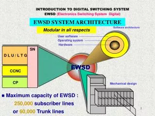
Brief History of Digital Electronics • Digital electronics can be found in many applications in the form of microprocessors, microcontrollers, PCs, DSPs, and an uncountable number of other systems. • The design of digital circuits has progressed from resistor-transistor logic (RTL) and diode-transistor logic (DTL) to transistor-transistor logic (TTL) and emitter-coupled logic (ECL) to NMOS and now Complementary MOS (CMOS) • The density and number of transistors in microprocessors has increased from 2300 in the 1971 4-bit 4004 microprocessor to 25 million in the more recent IA-64 chip, chips employing more than 1 B transistors have been introduced and it is projected to reach over 10 billion transistors by 2018. Microelectronic Circuit Design, 4E McGraw-Hill
Ideal Logic Gates • Binary logic gates are the most common style of digital logic • The output will consist of either a 0 (low) or a 1 (high) • (Positive Logic Convention) • The most basic digital building block is the inverter Microelectronic Circuit Design, 4E McGraw-Hill
The Ideal Inverter The ideal inverter has the following voltage transfer characteristic (VTC) and is described by the following symbol V+ and V- are the supply rails, and VH and VL describe the high and low logic levels at the output Microelectronic Circuit Design, 4E McGraw-Hill
Logic Level Definitions An inverter operating with power supplies at V+ and 0 V can be implemented using a switch with a resistive load Microelectronic Circuit Design, 4E McGraw-Hill
Logic Voltage Level Definitions • VL – The nominal voltage corresponding to a low-logic state at the output of a logic gate for vi = VH • VH – The nominal voltage corresponding to a high-logic state at the output of a logic gate for vi = VL • VIL – The maximum input voltage that will be recognized as a low input logic level • VIH – The minimum input voltage that will be recognized as a high input logic level • VOH – The output voltage corresponding to an input voltage of VIL • VOL – The output voltage corresponding to an input voltage of VIH Microelectronic Circuit Design, 4E McGraw-Hill
Logic Voltage Level Definitions (cont.) Note that for the voltage transfer characteristic (VTC) of the nonideal inverter, there is now an undefined logic state. Microelectronic Circuit Design, 4E McGraw-Hill
CMOS FET/Transistor 速度如何決定? • 台積電 (TSMC) 如何從製程中得到營業利益? 如何超越別的競爭? IC (CMOS FET) 速度如何加快? 製程Scaling 如何影響? 速度, 熱量, 晶片密度 如何與製程Scaling(alpha factor) 產生關聯? Microelectronic Circuit Design, 4E McGraw-Hill
Noise Margins • Noise margins represent “safety margins” that prevent the circuit from producing erroneous outputs in the presence of noisy inputs • Noise margins are defined for low and high input levels using the following equations: one’s output is the input of next stage NML = VIL – VOL NMH = VOH – VIH Microelectronic Circuit Design, 4E McGraw-Hill
Noise Margins (cont.) • Graphical representation of where noise margins are defined Microelectronic Circuit Design, 4E McGraw-Hill
Logic Gate Design Goals • An ideal logic gate is highly nonlinear and attempts to quantize the input signal to two discrete states. In an actual gate, the designer should attempt to minimize the undefined input region while maximizing noise margins • The input should produce a well-defined output, and changes at the output should have no effect on the input • Voltage levels at the output of one gate should be compatible with the input levels of a following gate • The gate should have sufficient fan-out and fan-in capabilities • The gate should consume minimal power (and area for ICs) and still operate under the design specifications Microelectronic Circuit Design, 4E McGraw-Hill
Dynamic Response of Logic Gates • An important figure of merit to describe logic gates is the response in the time domain • The rise and fall times, tf and tr, are measured at the 10% and 90% points on the transitions between the two states as shown by the following expressions: V10% = VL + 0.1V V90% = VL + 0.9V = VH – 0.1V where V is the logic swing given by V = VH - VL Microelectronic Circuit Design, 4E McGraw-Hill
Propagation Delay • Propagation delay describes the amount of time between a the input reaching the 50% point and the output reaching the 50% point. The 50% point is described by the following: • The high-to-low propagation delay, PHL, and the low-to-high propagation delay, PLH, are usually not equal, but can be combined as an average value: Microelectronic Circuit Design, 4E McGraw-Hill
Circuit Delay– RC circuit Microelectronic Circuit Design, 4E McGraw-Hill
Delay calculation • What is the charge of a capacitor C when applied a voltage of V? Answer: Q = C*V When a capacitor is connected with a resistor R, and initial voltage of capacitor is V, what will be the voltage vs time plot? dQ(t)/dt = current = I(t), I(t)*R = Vr, Microelectronic Circuit Design, 4E McGraw-Hill
Homework #2 • 4.2, 4.15, 4.37, 4.79, 4.80 Microelectronic Circuit Design, 4E McGraw-Hill
Dynamic Response of Logic Gates Microelectronic Circuit Design, 4E McGraw-Hill
Power Delay Product • The power-delay product (PDP) is used as a metric to describe the amount of energy (Joules) required to perform a basic logic operation and is given by the following equation where P is the average power dissipated by the logic gate: Microelectronic Circuit Design, 4E McGraw-Hill
Review of Boolean Algebra (11/7) NOT Truth Table OR Truth Table AND Truth Table NOR Truth Table NAND Truth Table Microelectronic Circuit Design, 4E McGraw-Hill
Logic Gate Symbols and Boolean Expressions Microelectronic Circuit Design, 4E McGraw-Hill
NMOS Logic Design • MOS transistors (both PMOS and NMOS) can be combined with resistive loads to create single channel logic gates • The circuit designer is limited to altering circuit topology and the width-to-length (W/L) ratio since the other factors are dependent upon processing parameters Microelectronic Circuit Design, 4E McGraw-Hill
NMOS Inverter with a Resistive Load • The resistor R is used to “pull” the output high • MS is the switching transistor used to “pull” the output low • The size of R and the W/L ratio of MS are the design factors that need to be chosen Microelectronic Circuit Design, 4E McGraw-Hill
Load Line Visualization The operation of the NMOS output (iD, vDS) characteristics. Load line equation: Microelectronic Circuit Design, 4E McGraw-Hill
NMOS with Resistive LoadDesign Example • Design a NMOS resistive load inverter for • VDD = 3.3 V • P = 0.1 mW when VL = 0.2 V • Kn = 60 A/V2 • VTN = 0.75 V • Find the value of the load resistor R and the W/L ratio of the switching transistor MS Microelectronic Circuit Design, 4E McGraw-Hill
Example continued • First the value of the current through the resistor (for vO = VL) must be determined by using the following: • The value of the resistor can now be found by the following which assumes that the transistor is on and the output is low: Microelectronic Circuit Design, 4E McGraw-Hill
Example Continued • For vI = VH = 3.3 V, and vO = VL = 0.2V, the transistor’s drain-source voltage VDS will be less than VGS -VTN. Therefore it will be operating in the triode region. Using the triode region equation for the MOSFET, the W/L ratio can be found: Microelectronic Circuit Design, 4E McGraw-Hill
On-Resistance of the Switching Device, MS • The NMOS resistive load inverter can be thought of as a resistive divider when the output is low, described by the following expression: Microelectronic Circuit Design, 4E McGraw-Hill
On-Resistance of MS (cont.) When the NMOS resistive load inverter’s output is low, the On-Resistance Ron of the NMOS can be calculated with the following expression: Note that Ron should be kept small compared to R to ensure that VL remains low, and also that its value is nonlinear, since it has a dependence on vDS Microelectronic Circuit Design, 4E McGraw-Hill
Load Resistor Problems • For completely integrated circuits, R must be implemented on chip using the shown structure • Using the given equation, it can be seen that resistors take up a large area of silicon as in an example 95k resistor Microelectronic Circuit Design, 4E McGraw-Hill
Using Transistors in Place of a Resistor NMOS load with a) gate connected to the source b) gate connected to ground c) gate connected to VDD d) gate biased to linear region e) a depletion-mode NMOSFET f) gate grounded PMOS load Note that a) and b) are not useful. (ML always off.) Microelectronic Circuit Design, 4E McGraw-Hill
Static Design of the NMOS Saturated Load Inverter Schematic for a NMOS saturated load inverter Cross-section for a NMOS saturated load inverter Microelectronic Circuit Design, 4E McGraw-Hill
NMOS Saturated Load Inverter Design Strategy • Given VDD, VL, and the power level, find IDD from VDD and power • Assume MS off, and find high output voltage level VH • Use the value of VH for the gate voltage of MS and calculate (W/L)S of the switching transistor based on the design values of IDD and VL • Find (W/L)L (load transistor) based on IDD and VL • Check the operating region assumptions of MS and ML for vo = VL • Verify design with a SPICE simulations Microelectronic Circuit Design, 4E McGraw-Hill
NMOS Saturated Load Inverter Design Example • Design an saturated load inverter given the following specifications: Microelectronic Circuit Design, 4E McGraw-Hill
NMOS Saturated Load Inverter Design Example • First find VH (The output cannot exceed the positive power supply voltage.) Microelectronic Circuit Design, 4E McGraw-Hill
NMOS Saturated Load Inverter Design Example (11/14) • For vo = VL, MS is on (in the triode region), and ML is in saturation. • Find the W/L ratios of the two transistors Microelectronic Circuit Design, 4E McGraw-Hill
NMOS Inverter Summary • Resistive load inverter takes up too much area for and IC design. • The saturated load configuration is the simplest design, but VH never reaches VDD, and it has a slow switching speed. • The linear load inverter fixes the speed and logic level issues, but it requires an additional power supply for the load gate. • The depletion-mode NMOS load requires the most processing steps, but needs small area to achieve the high speed, VH = VDD, and best combination of noise margins. • The Pseudo NMOS inverter offers the best speed with the lowest area. Microelectronic Circuit Design, 4E McGraw-Hill
Typical Inverter Characteristics Microelectronic Circuit Design, 4E McGraw-Hill
Reference Inverter Designs for Later Sections Microelectronic Circuit Design, 4E McGraw-Hill
NOR Gates Simplified switch model for the NOR gate with MA on Two-input NOR gate Microelectronic Circuit Design, 4E McGraw-Hill
NAND Gates Simplified switch model for the NOR gate with A and B on (right) Two-input NAND gate (left) Microelectronic Circuit Design, 4E McGraw-Hill
NAND Gate Device Size Selection • The NAND switching transistors can be sized based on the depletion-mode load inverter • To keep the low voltage level comparable with the inverter, the desired Ron of MA and MB must be 0.5Ron of MS,Inverter • This can be accomplished by approximately doubling (W/L)A and (W/L)B • The sizes can also be chosen by using the design value of VL and using the following equation: Microelectronic Circuit Design, 4E McGraw-Hill
NAND Gate Device Size Selection (cont.) • Two sources of error that arise are the facts that the VSB’s and VGS’s of the two transistors are not equal. These factors should be considered for proper gate design • The technique used to calculate the size of the load transistor for the NAND gate is exactly the same as for the depletion-load inverter Microelectronic Circuit Design, 4E McGraw-Hill
Layout of the NMOS Depletion-Mode NOR and NAND Gates Microelectronic Circuit Design, 4E McGraw-Hill
6.9 Complex NMOS Logic Design An advantage of NMOS technology is that it is simple to design complex logic functions based on the NOR and NAND gates The circuit in the figure has the logic function: Y = A + BC + BD Microelectronic Circuit Design, 4E McGraw-Hill
Complex Logic Gate Transistor Sizing • There are two ways to find the W/L ratios of the switching transistors • Use the worst-case path (most devices in series) and choose the W/L ratios to achieve the value of Ron equivalent to that of the inverter • Partitioning the circuit into a series sub-networks, and make the equivalent on-resistances equal Microelectronic Circuit Design, 4E McGraw-Hill
Complex Logic Gate Transistor Sizing The figure on the left shows the worst case technique to find the sizes where (W/L)S = 2.06 is the reference inverter ratio for this technology and the longest path is 3 transistors are in series The figure on the right shows the partitioning technique to find the sizes which gives two 4.12/1 ratios in series which is 2(2.06/1) Microelectronic Circuit Design, 4E McGraw-Hill