Download
1 / 17
170 likes | 185 Views
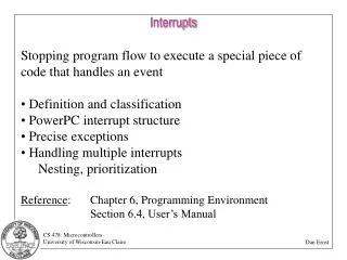
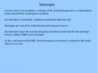
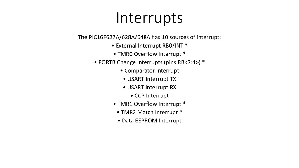
Interrupts. The PIC16F627A/628A/648A has 10 sources of interrupt : • External Interrupt RB0/INT * • TMR0 Overflow Interrupt * • PORTB Change Interrupts (pins RB<7:4 >) * • Comparator Interrupt • USART Interrupt TX • USART Interrupt RX • CCP Interrupt

E N D
Interrupts The PIC16F627A/628A/648A has 10 sources of interrupt: • External Interrupt RB0/INT * • TMR0 Overflow Interrupt * • PORTB Change Interrupts (pins RB<7:4>) * • Comparator Interrupt • USART Interrupt TX • USART Interrupt RX • CCP Interrupt • TMR1 Overflow Interrupt * • TMR2 Match Interrupt * • Data EEPROM Interrupt
Interrupts • IMPORTANT!!! We need to access two different registers: INTCON and OPTION. INTCON is in bank 0, OPTION is in bank 1
Interruptsto enable interrupts:bsf INTCON,GIE or bsf INTCON,7
Interrupts: let’s focus on local interruptsTMR0- Timer 0 alarm has gone offB0 – change on pin B0RB PORT Change- change on one of B4,B5,B6,B7
InterruptsSuppose we wish to interrupt on :- change on B0- when TMR0 alarms sounds bsf INTCON, GIE ; enable global interrupts bsf INTCON,INTE ; enable change of B0 interrupt bsf INTCON,TMIE ; enable Timer 0 interrupt
Interrupts • Each local interrupt enable bit has a corresponding flag bit. The flag indicates that this type of interrupt has occurred: • INTEINTF (B0 change ) • TOIETOIF (Timer0 alarm) • RBIERBIF (change on B4,B5,B6, or B7)
Interrupts:INTE versus RBIE INTE occurs with a change on B0. The programmer decides if the desired interrupt change is from low to high or high to low. This is specified in the OPTION register bit 6 (INTEDG) RBIE occurs with any change of state on pins B4,B5,B6,B7
Interrupts Let’s set an interrupt on B0 on a rising edge: bsf INTCON,GIE ; enable global interrupts bsf INTCON,INTE ; enable B0 interrupt bsf STATUS,RP0 ; goto bank 1movlw0x01 movwfTRISB ; portb pin 0 is input bsf OPTION, INTEDG ; interrupt on low to highbcf STATUS,RP0 ; ;return to bank 0
Interrupts • Interrupt Service Routines (ISR) always end with retfie • When an interrupt occurs, the GIE is set to 0. Thus, an interrupt cannot occur while an interrupt is occurring. • retfie re-enables GIE • Interrupts do “stack”. That is, if an interrupt occurs while an interrupt is being serviced, the new interrupt will be serviced after the older interrupt finishes and retfie re-enables interrupts • When an interrupt occurs, only the PC is saved on a stack. The programmer must save any other registers (like the W???) • NEVER set or clear GIE in an interrupt routine
Timer 0 • Timer 0 (TMR0) is an 8-bit register in bank 0 • TMR0 will set the Timer 0 flag (T0IF) on overflow from 0xff to 0x00 • T0IF will be set even if interrupts are not enabled (true for all interrupt flags) • TMR0 will “tick” either from the system clock or from transitions externally (pin A4) • We are interested in using Timer 0 with the system clock
Timer 0 Timer 0 users a “prescaler”. Think of the PIC as ticking every 1 microsecond. We can set different prescalers so that Timer 0 increments at a slower pace. Timer 0 has prescalers as follows: 2:1 increment every 2 microseconds 4:1 increment every 4 microseconds ….. 256:1 increment every 256 microseconds So Timer 0 can actually give time upto 65,536 microseconds. Note, there is no 1:1 prescaler.
Timer 0: revisit OPTION register (bank 1)bcf OPTION,TOCS ; use internal clock
Timer 0 – revisit OPTION registerbcf OPTION,PSA ; select Timer0, not watch dog timerbcf OPTION,2 ; next three set prescaler to 2:1bcf OPTION,1bcf OPTION,0
Timer 0 – 500 microsecond timer, no interrupt • Let’s see: we’ll need 250 “clicks” of the timer with a 2:1 prescaler. So we will load TMR0 with the value 0x06. bsf STATUS,RP0 ; goto bank 1 ; select system clock (bit 5), TMR0(bit 3), prescaler 2:1( bits 2-0)movlw 0x00 movwf OPTION ; set bits 5,3,0-2bcf STATUS,RP0 ;return to bank 0 movlw 0x06 movwf TMR0 ; place a 6 in timer btfss INTCON,T0IF ; overflow? goto $-1
Timer 0 – generate an interrupt in 500 microseconds (set up is in main) bsf INTCON,GIE ; enable global interrupts bsfINTCON,T0IE ; enable Timer 0 interrupt bsf STATUS,RP0 ; goto bank 1movlw 0x00 ; system clock, timer 0, 2:1 prescalermovwf OPTION ; portb pin 0 is inputbcf STATUS,RP0 ; ;return to bank 0 movlw 0x06 movwf TMR0 Blah blah blah ; go on your merry way, interrupt in 500 micros
Coding it main must reside at 0x00 and ISR must reside at 0x04. Typical layout: org 0x00 goto main org 0x04 gotoisr isr …... ...... retfie main ...... ...... end
Coding it • An interrupt clears GIE, retfie resets it. Leave it alone!! • An interrupt sets the specific interrupt flag. You must clear it before you execute retfie. Otherwise, the interrupt will never occur again. • If you have enabled several interrupts, your interrupt routine must poll the interrupt flags to determine which interrupts occurred. You may service multiple interrupts in a routine. If you don’t, the subsequent interrupts will be triggered immediately upon executing a retfie.