Download
1 / 39
440 likes | 738 Views
Cables why cables? coupling in cables effect on field error in magnets Quenching the quench process, internal and external voltages decay times and temperature rise propagation of the normal zone quench protection schemes protection of LHC. Lecture 3: Cables and quenching .

E N D
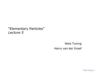
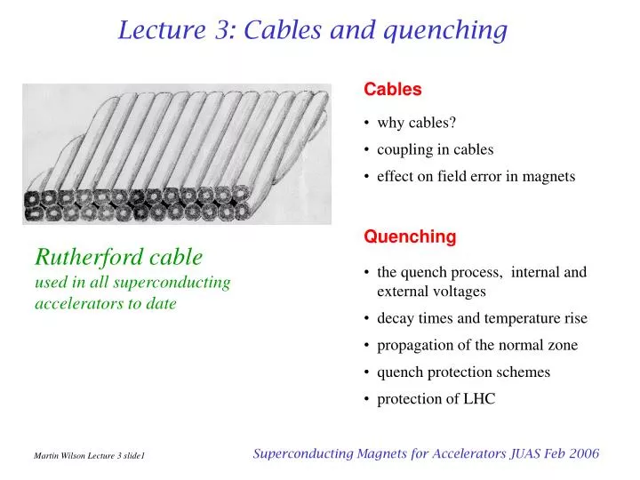
Cables why cables? coupling in cables effect on field error in magnets Quenching the quench process, internal and external voltages decay times and temperature rise propagation of the normal zone quench protection schemes protection of LHC Lecture 3: Cables and quenching Rutherford cable used in all superconducting accelerators to date Superconducting Magnets for Accelerators JUAS Feb 2006
for good tracking we connect synchrotron magnets in series if the stored energy is E, rise time t and operating current I , the charging voltage is Why cables? • RHICE = 40kJ/m, t = 75s, 30 strand cable • cable I = 5kA, charge voltage per km = 213V • wire I = 167A, charge voltage per km = 6400V • FAIR at GSIE = 74kJ/m, t = 4s, 30 strand cable • cable I = 6.8kA, charge voltage per km = 5.4kV • wire I = 227A, charge voltage per km = 163kV • so we need high currents! the RHIC tunnel • a single 5mm filament of NbTi in 6T carries 50mA • a composite wire of fine filaments typically has 5,000 to 10,000 filaments, so it carries 250A to 500A • for 5 to 10kA, we need 20 to 40 wires in parallel - a cable Superconducting Magnets for Accelerators JUAS Feb 2006
cables carry a large current and this generates a self field in this cable the self field generates a flux between the inner and outer wires wire are twisted to avoid flux linkage between the filaments, for the same reasons we should avoid flux linkage between wires in a cable but twisting this cable doesn't help because the inner wires are always inside and the outers outside Types of cable I Bs • thus it is necessary for the wires to be fully transposed, ie every wire must change places with every other wire along the length of the cable so that, averaged over the length, no flux is enclosed • three types of fully transposed cable have been tried in accelerators • - rope • - braid • - Rutherford Superconducting Magnets for Accelerators JUAS Feb 2006
Rutherford cable • the cable is insulated by wrapping 2 or 3 layers of Kapton; gaps may be left to allow penetration of liquid helium; the outer layer is treated with an adhesive layer for bonding to adjacent turns. • Note: the adhesive faces outwards, don't bond it to the cable (avoid energy release by bond failure, which could quench the magnet ) Superconducting Magnets for Accelerators JUAS Feb 2006
Rutherford cable • The main reason why Rutherford cable succeeded where others failed was that it could be compacted to a high density (88 - 94%) without damaging the wires. Furthermore it can be rolled to a good dimensional accuracy (~ 10mm). • Note the 'keystone angle', which enables the cables to be stacked closely round a circular aperture Superconducting Magnets for Accelerators JUAS Feb 2006
Ra Rc Coupling in Rutherford cables • Field transverse coupling via crossover resistance Rc crossover resistance Rc adjacent resistance Ra • Field parallel • coupling via adjacent resistance Ra • Field transverse coupling via adjacent resistance Ra Superconducting Magnets for Accelerators JUAS Feb 2006
Magnetization from coupling in cables B` 2b 2c • Field transverse coupling via crossover resistance Rc where M = magnetization per unit volume of cable, p twist pitch, N = number of strands • Field transverse coupling via adjacent resistance Ra where q = slope angle of wires Cosq~ 1 (usually negligible) • Field parallel • coupling via adjacent resistance Ra • Field transverse • ratio crossover/adjacent So without increasing loss too much can make Ra 50 times less than Rc - anisotropy Superconducting Magnets for Accelerators JUAS Feb 2006
Controlling Ra and Rc • surface coatings on the wires are used to adjust the contact resistance • the values obtained are very sensitive to pressure and heat treatments used in coil manufacture (to cure the adhesive between turns) • data from David Richter CERN Cored Cables • using a resistive core allows us to increase Rc preferentially • not affected by heat treatment Superconducting Magnets for Accelerators JUAS Feb 2006
Long range coupling: BICCs • measuring the field of an accelerator magnet along the beam direction, we find a ripple • wavelength of this ripple exactly matches the twist pitch of the cable • thought to be caused by non uniform current sharing in the cable • Verweij has called them 'boundary induced coupling currents' BICCs • they are caused by non uniform flux linkages or resistances in the cable, eg at joints, coil ends, manufacturing errors etc. • wavelength is << betatron wavelength so no direct problem, but interesting secondary effects such as 'snap back'. sextupole measured in SSC dipole at injection and full field Superconducting Magnets for Accelerators JUAS Feb 2006
Field errors caused by coupling • plot of sextupole field error in an LHC dipole with field ramped at different rates • error at low field due to filament magnetization • error at high field due to a) iron saturation b) coupling between strands of the cable • the curves turn 'inside out' because - greatest filament magnetization is in the low field region (high Jc) - greatest coupling is in the high field region (high dB/dt) data from Luca Bottura CERN Superconducting Magnets for Accelerators JUAS Feb 2006
Cables: concluding remarks • accelerator magnets need high currents cables - cables must be fully transposed - Rutherford cable used in all accelerators to date • can get coupling between strands in cables - causes additional magnetization field error - control coupling by oxide layers on wires or resistive core foils Superconducting Magnets for Accelerators JUAS Feb 2006
Part 2: Quenching the most likely cause of death for a superconducting magnet • Plan • the quench process • decay times and temperature rise • propagation of the resistive zone • resistance growth and decay times • quench protection schemes • case study: LHC protection Superconducting Magnets for Accelerators JUAS Feb 2006
Magnetic stored energy Magnetic energy density at 10T E= 4x10⁷ Joule.m-3 at 5T E = 107 Joule.m-3 LHC dipole magnet (twin apertures) E = ½ LI 2L = 0.12HI = 11.5kA E = 7.8 x 10⁶ Joules the magnet weighs 26 tonnes so the magnetic stored energy is equivalent to the kinetic energy of:- 26 tonnes travelling at 88km/hr Superconducting Magnets for Accelerators JUAS Feb 2006
The quench process • resistive region starts somewhere in the winding at a point- this is the problem! • it grows by thermal conduction • stored energy½LI2of the magnet is dissipated as heat • greatest integrated heat dissipation is at point where the quench starts • internal voltages much greater than terminal voltage ( = Vcs current supply) • maximum temperature may be calculated from the current decay time via the U(q)function (adiabatic approximation) Superconducting Magnets for Accelerators JUAS Feb 2006
The temperature rise function U(q) or the 'fuse blowing' calculation (adiabatic approximation) J(T) = overall current density, T = time, r(q) = overall resistivity, g = density, q = temperature, C(q) = specific heat, TQ= quench decay time. • GSI 001 dipole winding is 50% copper, 22% NbTi, 16% Kapton and 3% stainless steel • NB always use overall current density Superconducting Magnets for Accelerators JUAS Feb 2006
Measured current decay after a quench Dipole GSI001 measured at Brookhaven National Laboratory Superconducting Magnets for Accelerators JUAS Feb 2006
Calculating the temperature rise from the current decay curve J 2 dt (measured) U(q) (calculated) Superconducting Magnets for Accelerators JUAS Feb 2006
Calculated temperature • calculate the U(q) function from known materials properties • measure the current decay profile • calculate the maximum temperature rise at the point where quench starts • we now know if the temperature rise is acceptable - but only after it has happened! • need to calculate current decay curve before quenching Superconducting Magnets for Accelerators JUAS Feb 2006
Growth of the resistive zone the quench starts at a point and then grows in three dimensions via the combined effects of Joule heating and thermal conduction * Superconducting Magnets for Accelerators JUAS Feb 2006
Quench propagation velocity 1 • resistive zone starts at a point and spreads outwards • the force driving it forward is the heat generation in the resistive zone, together with heat conduction along the wire • write the heat conduction equations with resistive power generation J2r per unit volume in left hand region and r = 0 in right hand region. resistive v qt temperature superconducting qo xt distance where: k = thermal conductivity, A = area occupied by a single turn,g = density,C = specific heat,h = heat transfer coefficient,P = cooled perimeter, r= resistivity, qo = base temperature Note: all parameters are averaged over A the cross section occupied by one turn assume xt moves to the right at velocity v and take a new coordinatee = x-xt= x-vt Superconducting Magnets for Accelerators JUAS Feb 2006
Quench propagation velocity 2 Jc rCu Jop reff qc qo qs qc qo qs qt when h = 0, the solution for q which gives a continuous join between left and right sides at qt gives the adiabatic propagation velocity recap Wiedemann Franz Law r(q).k(q) = Loq • what to say about qt ? • in a single superconductor it is just qc • but in a practical filamentary composite wire the current transfers progressively to the copper • current sharing temperature qs = qo + margin • zero current in copper below qs all current in copper above qs • take a mean transition temperature qs = (qs + qc )/2 Superconducting Magnets for Accelerators JUAS Feb 2006
Quench propagation velocity 3 av av v the resistive zone also propagates sideways through the inter-turn insulation (much more slowly) calculation is similar and the velocity ratio a is: Typical values a = 0.01 - 0.03 vad = 5 - 20 ms-1 so the resistive zone advances in the form of an ellipsoid, with its long dimension along the wire Some corrections for a better approximation • because C varies so strongly with temperature, it is better to calculate an averaged C from the enthalpy change • heat diffuses slowly into the insulation, so its heat capacity should be excluded from the averaged heat capacity when calculating longitudinal velocity - but not transverse velocity • if the winding is porous to liquid helium (usual in accelerator magnets) need to include a time dependent heat transfer term • can approximate all the above, but for a really good answer must solve (numerically) the three dimensional heat diffusion equation or, even better, measure it! Superconducting Magnets for Accelerators JUAS Feb 2006
Computation of resistance growth and current decay vdt vdt avdt avdt start resistive zone 1 * in time dt zone 1 grows v.dt longitudinally and a.v.dt transversely temperature of zone grows by dq1 =J2 r(q1)dt / g C(q1) resistivity of zone 1 isr(q1) calculate resistance and hence current decay dI = R / L.dt in time dt add zone n: v.dt longitudinal and a.v.dt transverse temperature of each zone grows by dq1 =J2r(q1)dt/gC(q1) dq2 =J2r(q2)dt/gC(q2) dqn=J2r(q1)dt /gC(qn) resistivity of each zone isr(q1) r(q2) r(qn) resistance r1= r(q1) * fg1(geom factor) r2= r(q2) * fg2rn= r(qn) * fgn calculate total resistance R = r1+ r2 +rn..and hence current decay dI = (IR/L)dt when I 0 stop Superconducting Magnets for Accelerators JUAS Feb 2006
Quench starts in the pole region * * * * * * the geometry factor fg depends on where the quench starts in relation to the coil boundaries Superconducting Magnets for Accelerators JUAS Feb 2006
Quench starts in the mid plane * * * Superconducting Magnets for Accelerators JUAS Feb 2006
Computer simulation of quench (dipole GSI001) pole block 2nd block mid block Superconducting Magnets for Accelerators JUAS Feb 2006
Computer simulation of quench temperature rise pole block 2nd block mid block Superconducting Magnets for Accelerators JUAS Feb 2006
Methods of quench protection:1) external dump resistor • detect the quench electronically • open an external circuit breaker • force the current to decay with a time constant where • calculate qmaxfrom Note: circuit breaker must be able to open at full current against a voltage V = I.Rp (expensive) Superconducting Magnets for Accelerators JUAS Feb 2006
Methods of quench protection:2) quench back heater • detect the quench electronically • power a heater in good thermal contact with the winding • this quenches other regions of the magnet, effectively forcing the normal zone to grow more rapidly higher resistance shorter decay time lower temperature rise at the hot spot method most commonly used in accelerator magnets Note: usually pulse the heater by a capacitor, the high voltages involved raise a conflict between:- - good themal contact - good electrical insulation Superconducting Magnets for Accelerators JUAS Feb 2006
Methods of quench protection:3) quench detection (a) I internal voltage after quench V • not much happens in the early stages - small dI/dt small V • but important to act soon if we are to reduce TQ significantly • so must detect small voltage • superconducting magnets have large inductance large voltages during charging • detector must reject V = LdI/dt and pick up V = IR • detector must also withstand high voltage -as must the insulation t Superconducting Magnets for Accelerators JUAS Feb 2006
Methods of quench protection:3) quench detection (b) i) Mutual inductance • ii) Balanced potentiometer • adjust for balance when not quenched • unbalance of resistive zone seen as voltage across detector D • if you worry about symmetrical quenches connect a second detector at a different point detector subtracts voltages to give • adjust detector to effectively make L = M • M can be a toroid linking the current supply bus, but must be linear - no iron! Superconducting Magnets for Accelerators JUAS Feb 2006
Methods of quench protection:4) Subdivision I • resistor chain across magnet - cold in cryostat • current from rest of magnet can by-pass the resistive section • effective inductance of the quenched section is reduced reduced decay time • reduced temperature rise • current in rest of magnet increased by mutual inductance effects • quench initiation in other regions • often use cold diodes to avoid shunting magnet when charging it • diodes only conduct (forwards) when voltage rises to quench levels • connect diodes 'back to back' so they can conduct (above threshold) in either direction Superconducting Magnets for Accelerators JUAS Feb 2006
Methods of quench protection:4b) Subdivision with quench back heater • arrange for the subdividing resistors to be in thermal contact with the winding • each resistor to contact a remote section of winding – spread the quench around Superconducting Magnets for Accelerators JUAS Feb 2006
Methods of quench protection:5) coupled secondary • arrange for the winding to be closely coupled to a short circuited secondary • typically the secondary will be the former on which the coil is wound. • the short circuited secondary reduces the effective inductance of the primary - hence decay time is reduced • in addition, the secondary should be in thermal contact with the winding so that it quenches other regions Superconducting Magnets for Accelerators JUAS Feb 2006
LHC power supply circuit for one octant circuit breaker • diodes allow the octant current to by-pass the magnet which has quenched • circuit breaker reduces to octant current to zero with a time constant of 100 sec • initial voltage across breaker = 2000V • stored energy of the octant = 1.33GJ Superconducting Magnets for Accelerators JUAS Feb 2006
Case study: LHC dipole protection • It's difficult! - the main challenges are: • 1) Series connection of many magnets • In each octant, 154 dipoles are connected in series. If one magnet quenches, the combined inductance of the others will try to maintain the current. Result is that the stored energy of all 154 magnets will be fed into the magnet which has quenched vaporization of that magnet!. • Solution 1: put cold diodes across the terminals of each magnet. In normal operation, the diodes do not conduct - so that the magnets all track accurately. At quench, the diodes of the quenched magnet conduct so that the octant current by-passes that magnet. • Solution 2: open a circuit breaker onto a dump resistor (several tonnes) so that the current in the octant is reduced to zero in ~ 100 secs. • 2) High current density, high stored energy and long length • As a result of these factors, the individual magnets are not self protecting. If they were to quench alone or with the by-pass diode, they would still burn out. • Solution 3: Quench heaters on top and bottom halves of every magnet. Superconducting Magnets for Accelerators JUAS Feb 2006
LHC quench-back heaters • stainless steel foil 15mm x 25 mm glued to outer surface of winding • insulated by Kapton • pulsed by capacitor 2 x 3.3 mF at 400 V = 500 J • quench delay - at rated current = 30msec - at 60% of rated current = 50msec • copper plated 'stripes' to reduce resistance Superconducting Magnets for Accelerators JUAS Feb 2006
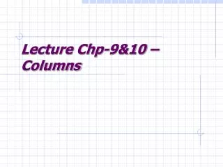
Diodes to by-pass the main ring current Installing the cold diode package on the end of an LHC dipole Superconducting Magnets for Accelerators JUAS Feb 2006
Quenching: concluding remarks • magnets store large amounts of energy - during a quench this energy gets dumped in the winding intense heating (J ~ fuse blowing) possible death of magnet • temperature rise and internal voltage can be calculated from the current decay time • computer modelling of the quench process gives an estimate of decay time – but must decide where the quench starts • if temperature rise is too much, must use a protection scheme • active quench protection schemes use quench heaters or an external circuit breaker - need a quench detection circuit which must reject LdI/dt and be 100% reliable • passive quench protection schemes are less effective because V grows so slowly - but are 100% reliable • protection of accelerator magnets is made more difficult by series connection - all the other magnets feed their energy into the one that quenches • for accelerator magnets use by-pass diodes and quench heaters • remember the quench when designing the magnet insulation always do the quench calculations before testing the magnet Superconducting Magnets for Accelerators JUAS Feb 2006