Download
1 / 16
160 likes | 337 Views
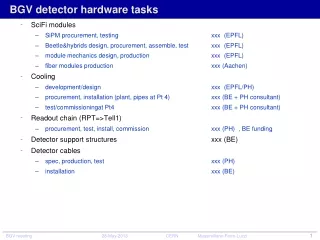
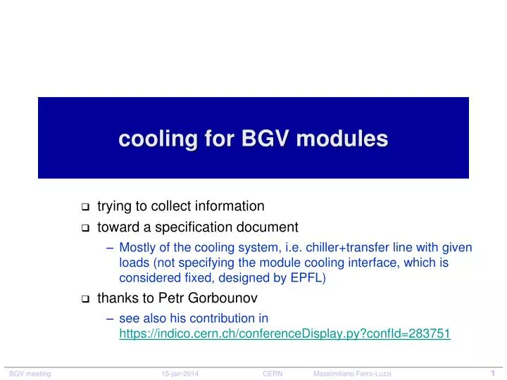
cooling for BGV modules. trying to collect information toward a specification document Mostly of the cooling system, i.e. chiller+transfer line with given loads (not specifying the module cooling interface, which is considered fixed, designed by EPFL) thanks to Petr Gorbounov

E N D
cooling for BGV modules trying to collect information toward a specification document Mostly of the cooling system, i.e. chiller+transfer line with given loads (not specifying the module cooling interface, which is considered fixed, designed by EPFL) thanks to Petr Gorbounov see also his contribution in https://indico.cern.ch/conferenceDisplay.py?confId=283751
Help from EN-CV ? Talked to MicheleBattistin (18 dec 2013) • They have no resources for integration/installation on short notice • But theycan help for dimensioning and technical contact withcompanies • Theyneedsomespecs: coolingstrategy, a sketch, acceptable T over modules, operating temperature at detector, acceptable temperature gradient over transfer line, pressure drop at detector (pipe diameter, series or parallel ?) • Integration: I. Muttoni • Note: Julabochilleris good, must howeveraskperhaps for specialpump (depending on required flow)
BGV module dry air in/out fiber mats electronics/flex ~26cm cooling fluid in/out thermal-insulating box (contains SiPM detectors that need to be kept cold)
BGV system composed of 8 modules, arranged in 2 stations (distance between stations is about 1m)
transfer line request General: • Single phase liquidcooling • Type of fluid: 3M NOVEC 649 or similar (radiation! ~ < 100 Gy/year) • not creepy, oily, ... KeepSiPM and electronics clean in case of fluidleaks!! • SiPMcooling pipe (2 per module): in/out diameter = 3/4 mm, 378 mm long, copper • 16 pipes in total, connected in series or parallel ... expect suggestion from TS-CV • Operating temperature (at detector): settablebetween20 and -40 C • Module inside (SiPM and pipe) isflushedwith dry air • Stability+/- 1K , gradient < 1K over one SiPM (thus 8K over one SiPMrow ?) • Assume 20 Wheatload per module ? (conservative) dominated by heatleaks (insulation) Transfer line: • Transfer line must befixed in place, beforeclosure of machine (2014) • Goes fromnear detector to justoutside the connectinghole • Total length (3D path) is about 20m (minimum) • Temperature drop over transfer line < 10 K (to avoid to lowchillertemperature) • Insulated, no frost • Acceptable pressure drop over transfer line: don't care ? • Must bedimensionedsuch as to allow flux of up to 20 l/min to bemeasured in lab as soon as possible turbulent flow: >0.5 l/min per SiPM pipe
transfer line: somepictures machine tunnel side (RA43) service tunnel side (UA43) the wallhole
sketch of BGV cooling tunnel wall dark box station 2 station 1 Thermal insulation up to module! module module module module module module module module service tunnel transfer line chiller dry air tunnel wall
BGV coolingspecs SiPM pipe: innner d = 3mm outer D = 4mm length L = 377.5 mm • Assume operating temperature: settable between20 and -40 C at detector • Stability +/- 1K • Assume 20 Wheat dissipation per SiPM module ? (conservative) • to beconfirmed by measurement! • Max temperature gradient over 1 SiPM: 0.5 K Max temperature gradient over 1 branch: 5K • Minimum flow F neededper branch to get turbulent flow: Take NOVEC: = 1766 g/dm3at -40C C = 1.1 J g-1K-1, k = 0.059 W m-1 K-1 = 0.64 cPkin. viscosity = 0.4 cSt http://www.pressure-drop.com/Online-Calculator/ Re = d v / = 4 F / ( d ) F = flow = v (d/2)2 heattransfercoeff: h = ~ 0.023 Re0.8 (k/d) Pr0.33 = ~0.32 Wcm-2K-1 Pr = C∙ / k = ~120 q = h ∙ A ∙ (Twall - Tfluid ) A = d L = 36 cm2 • Acceptable pressure drop over transfer line: don't care ? d velocity >10000 is turbulent take Re = 8842
LHCbchiller in point 8 (Petr Gorbounov) • example • called Julabo: do not guarantee it works in radiation (10-100Gy/yr)
chiller, more power • example • called Julabo: do not guarantee it works in radiation (10-100Gy/yr) getpicture at POINT8, what model ?
Coolant • C6F14 or NOVEC 649 ? • Try NOVEC 649 and get experience!