Download
1 / 17
190 likes | 404 Views
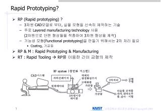
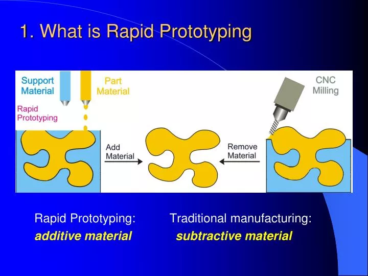
1. What is Rapid Prototyping. Rapid Prototyping: Traditional manufacturing: additive material subtractive material. 1.1 Characteristics of RP.

E N D
1. What is Rapid Prototyping Rapid Prototyping: Traditional manufacturing: additive material subtractive material
1.1 Characteristics of RP • A technology that produces models and prototype parts from 3D CAD model data, CT and MRI scan data, and model data created from 3D object digitizing systems • RP systems join together liquid, powder and sheet materials to form parts Layer by layer, RP machines fabricate plastic, wood, ceramic and metal objects RPalso known as Solid Freeform Fabrication (SFF) or Layer Manufacturing (LM)
CAD Model Surface/Solid Model Generate .STL file Build Prototype Remove Supports Clean Surface Build Supports if needed Post Cure if needed Slicing Part Completed 1.2 Basic process of RP Three stages: pre-processing, building, and post processing Pre Process RP Process Post Process in CAD in RP systems
Shorten time to market & reduced development cost THE COST OF CHANGE PHASE COST Conceptual modeling $10 Detail design $100 Prototype/test $1,000 Manufacturing $10,000 Product release $100,000 Source: Wohlers Associates 3D visualization of product designs Esure that customers have a clear understanding “A picture is worth a thousand words; a model is worth a thousand pictures.” 1.3 Benefits of RP Improved product quality RP enable more design iterations in a given time
2. Common types of RP • The first RP system was introduced in 1988 • Common types of RP technologies now: - StereoLithography (SL) - Fused Deposition Modeling (FDM) - Selective Laser Sintering (SLS) - Laminated Object Manufacturing (LOM) - 3D Printing (3DP)
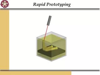
Scanning Mirror Laser Re-coating Blade Cured resin to form model Elevator & Platform Supports Liquid Resin 2.1 Stereo-Lithography (SL) 1. The elevator lowered by 1 layer deep; 2. The Blade sweep across the vat, apply an even layer of resin on top of the part; 3. As the laser beam strikes the resin surface, the liquid resin is hardened to a solid plastic; 4. Loop through the three steps to cure a new layer.
Representative: from 3D Systems, Inc. Materials: photocurable resins Adv. & Disadvantages: Good dimensional accuracy Good surface finish Narrow range of materials Relatively high cost Post curing Application areas: - Prototypes for concept models; - Form-fit for assembly tests and process planning; - Models for investment casting, replacement of the wax pattern; - Patterns for metal spraying, epoxy molding and other soft tooling Stereo-Lithography Apparatus (SLA)
Model & Support Filaments Heated extrusion head Part Support Elevator & Platform 2.2 Fused Deposition Modeling (FDM) 1. Extrusion head and elevator move to start position; 2. The head extrude layer of support; 3. The head extrude layer of model; 4. Loop through the three steps to build the next layer.
Representative: fromStratasys Inc. Materials: thermoplastic material such as wax, ABS plastic & elastomer Adv. & Disadvantages: clean, simple, easy to operate A good variety of material Mid range performance/cost Relative low accuracy Poor strength in vertical direction - Slow for building a mass part Application areas: - Conceptual modeling; - Fit, form and functional test; - Pattern for investment casting; - The MABS (methymethacrylate ABS) material is particularly suitable for medical applications. Fused Deposition Modeling (FDM)
Scanning Mirror Laser Roller Support Part Powder cartridges Build Chamber Piston 2.3 Selective Laser Sintering (SLS) 1. Piston of the part built chamber lower by one layer; 2. Piston of powder cartridges raise up; 3. Roller spread powder evenly over the built surface; 4. Laser beam scan over the top of the part, melting the powder and fuse it to the previous layer; 5. Loop through the four steps to build the next layer.
Representative: from DTM Corporation Materials: powder material such as nylon, wax, polycarbonate, metal, ceramic, elastomer, etc. Adv. & Disadvantages: Large variety of material available Produced in short time No additional support required No post curing required Heat up powder & cool down part Smoothness of surface restricted Expensive running cost Toxic gases generated Application areas: - Visual representation; - durable enough for most functional tests; - Pattern for making soft tooling, casting; - Direct manufacture of metal mould; - Small batch production run. Selective Laser Sintering (SLS)
2.4 Laminated Object Manufacturing (LOM) 1. The sheet material is stretched from the supply roller to the take-up roller; 2. The heated laminated roller passes over the sheet bonding it to the previous layer; 3. Laser cuts the profile of that layer and hatching the excess material for later removal; 4. Loop through the three steps to form a new layer.
Representative: from Helisys Materials: sheet material such as paper, plastic, ceramic, composite etc. Adv. & Disadvantages: A relatively high speed process No post curing required No support structure required Simple to use The most commonly used material is only paper Must be post processed immediately Restricted to build complex parts Fire hazard occasionally happened Application areas: - Visual representation; - Concept modeling; - Pattern for sand casting; Laminated Object Manufacturing (LOM)
2.5 3D Printing (3DP) Companies install them in offices near their CAD systems for concept modeling. less costly and less capable variation of RP technology
Common applications of the RP technology: Design concept models Marketing models for tenders, customer feedback, presentations and brochures Test & Analysis functional testing; strong models for wind tunnel and stress analysis Tooling masters and patterns for a broad range of manufacturing processes Medicine artificial limbs, tools and instruments 3. Application cases of RP
4. Rapid Tooling Making (RTM) • INDIRECT RPM: Pattern created by RP used to fabricate tool -RP-fabricated part as master in making silicon-rubber mold (subsequently used as production mold) - RP patterns to make sand molds for sand casting - Fabrication of patterns of low-melting pt. materials for Investment casting • DIRECT RPM: RP used to make the tool itself - 3D printing to create die geometry in metallic powders (followed by sintering & infiltration)
4. Rapid Tooling Making (RTM) • low volume(from tens to hundreds) -Soft Tooling • Intermediate (from hundreds to thousands) - Metal filled Epoxy Tooling - Powdered Metal Tooling Aluminum-filled epoxy mold, SL master, and molded thermoplastic parts