Download
1 / 17
170 likes | 366 Views
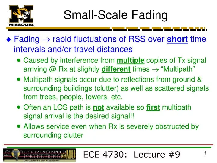
Small-Scale Fading. Fading rapid fluctuations of RSS over short time intervals and/or travel distances Caused by interference from multiple copies of Tx signal arriving @ Rx at slightly different times “Multipath”

E N D
Small-Scale Fading • Fading rapid fluctuations of RSS over short time intervals and/or travel distances • Caused by interference from multiple copies of Tx signal arriving @ Rx at slightly different times “Multipath” • Multipath signals occur due to reflections from ground & surrounding buildings (clutter) as well as scattered signals from trees, people, towers, etc. • Often an LOS path is not available so first multipath signal arrival is the desired signal!! • Allows service even when Rx is severely obstructed by surrounding clutter ECE 4730: Lecture #9
Small-Scale Fading • Multipath signals have randomly distributed amplitudes, phases, & direction of arrival • Vector summation (Aq ) @ Rx of multipath leads to constructive/destructive interference as mobile Rx moves in space (and time) • RSS can vary by 2030 dB over distances of only l/ 4 ! • l / 4 ~ 510 cm or 35 msec (for v = 40 mph) • Fading occurs about average RSS predicted from large-scale path loss models • Even fixed Tx/Rx wireless links can experience fading due to motion of objects (cars, people, trees, etc.) in surrounding environment ECE 4730: Lecture #9
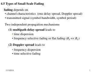
Mobile Radio Channel • Physical Factors Influencing Fading in Mobile Radio Channel (MRC) 1) Multipath Propagation • Number and strength of multipath signals • Time delay of signal arrival • Large path differences large delay • Urban area w/ many buildings distributed over large spatial scale • Large # of strong multipath signals with a few having large time delay • Suburb with nearby office park or shopping mall • Moderate # of strong multipath signals with small moderate delay times • Rural few multipath signals (LOS + ground reflection) ECE 4730: Lecture #9
Mobile Radio Channel • Physical Factors Influencing Fading in Mobile Radio Channel (MRC) 2) Speed of Mobile • Relative motion between base station & mobile causes random frequency modulation due to Doppler shift (fd) • fd = (v/l) cosq • Multipath signals will have different fd ’s for constant v b/c of random arrival directions (q)!! ECE 4730: Lecture #9
Doppler Shift fd = (v/l) cosq where v : velocity (m/s) l : wavelength (m) q : angle between mobile direction and arrival direction of RF energy + shift mobile moving toward S shift mobile moving away from S ECE 4730: Lecture #9
Mobile Radio Channel • Physical Factors Influencing Fading in Mobile Radio Channel (MRC) 3) Speed of Surrounding Objects • Also generates multipath signals with Doppler shift • Dominates small-scale fading if speed of objects > mobile speed • Otherwise ignored ECE 4730: Lecture #9
Mobile Radio Channel • Physical Factors Influencing Fading in Mobile Radio Channel (MRC) 4) Tx Signal Bandwidth (Bs) • MRC modeled as filter w/ specific bandwidth (BW) • Relationship between signal BW & MRC BW will determine: a) if small-scale fading is significant b) if time distortion of signal leads to inter-symbol interference (ISI) of transmitted digital data ECE 4730: Lecture #9
MRC Impulse Response • Model MRC as linear filter with ** time-varying ** impulse response • Filter model due to vector summation of random amplitudes & phases of multipath signals • Time variation due to mobile motion time delay of multipath signals varies with location of Rx! • MRC has fundamental bandwidth limitation model as BPF ECE 4730: Lecture #9
y(t) = x(t) h(t) or Y( f ) = X( f )H( f ) h(t) x(t) input y(t) output impulse response MRC Impulse Response • Linear filter theory • How is unknown h(t) determined? • Let x(t) = d(t) delta or impulse input then • y(t) = h(t) impulse response function (IRF) • IRF for standard filter theory is the same regardless of when it is measured time invariant! ECE 4730: Lecture #9
Multipath Echoes MRC IRF !! = hb ( t,t ) Tx Pulse time t = 0 first arrival @ t = to MRC Impulse Response • How is IRF of MRC determined? • “Channel sounding” Radar Fig. 5.6, pg. 192 • Transmit short time duration pulse (wide BW) and record multipath echoes @ Rx • Short duration Tx pulse unit impulse d(t) ! • Define excess delay time as t where t> to ECE 4730: Lecture #9
Channel Sounding ECE 4730: Lecture #9
MRC Impulse Response • Amplitude and delay time of multipath returns change as mobile moves • Fig. 5.4, pg. 184 MRC is time variant ECE 4730: Lecture #9
passband Hb (f) f MRC Impulse Response • Model multipath returns as unit impulses • aiqi = amplitude & phase of multipath signals (d ) • N = # of multipath components • FFT of IRF gives spectral characteristics of channel frequency response! • MRC filter passband “Channel BW” or Coherence BW = Bc ECE 4730: Lecture #9
Multipath Channel Parameters • Derived from multipath power delay profiles • P (t k) : relative power amplitudes of multipath signals • Use ensemble average of many profiles in small localized area typically 26 m obtain average small-scale response ECE 4730: Lecture #9
Multipath Channel Parameters • Time Dispersion Parameters • Mean excess delay • RMS delay spread • Typical values: • Outdoor channel ~ 13 msec • Indoor channel ~ 20100 nsec • Maximum excess delay (X dB): excess delay value during which multipath power levels fall X dB below the maximum power level • Worst case delay value • “Excess delay” : all values computed relative to time of first signal arrivalto(see figure on slide #10) ECE 4730: Lecture #9
Time Dispersion Parameters ECE 4730: Lecture #9
Time Dispersion Parameters ECE 4730: Lecture #9