Download
1 / 1
30 likes | 227 Views
Optimum Design of Mechanical System Requires structural and/or thermal analysis. Mostly utilizes commercial CAE codes such as ANSYS, NASTRAN in their analysis and/or optimization. CAE codes have however limitations in shape modeling.

E N D
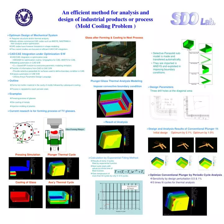
Optimum Design of Mechanical System • Requires structural and/or thermal analysis. • Mostly utilizes commercial CAE codes such as ANSYS, NASTRAN in their analysis and/or optimization. • CAE codes have however limitations in shape modeling. • Thus recent studies are focused on efficient CAD/CAE integration. Glass after Forming & Cooling to Next Process An efficient method for analysis and design of industrial products or process(Mold Cooling Problem ) • Selective Parasolid sub-model is made and transfered automatically. • They are imported in ANSYS and exploited in imposing boundary conditions. • CAD/CAEIntegration under Optimization S/W • CAD/CAE integration in optimization code • IDESIGN for optimization routine, Unigraphics for CAD, ANSYS for CAE. • Modeling automation in CAD S/W • C++ based API function to overcome parametric modeling limitation. • Transfer of informations from CAD to CAE S/W • Provide selective parasolids for surfaces used to define boundary condition in CAE. • Analysis automation in CAE S/W • Utilizes Ansys Parametric Design Language. • Outline • Forms hot molten material in the cavity of molds followed by subsequent cooling. • Process is repeated to reach periodic state. • Examples • Pressing process of glasses • Die-casting of metals • Injection molding of plastics • Current reseach is for forming process of TV glasses. • Plunger/Glass Thermal Analysis Modeling • Impose convective boundary condition • Design Parameters • Three drill holes at the diagonal area • Result of Analysis • Design and Analysis Results of Conventional Plunger 1h • Initial design Optimum by 0.1% Optimum by 1.0% Glass Forming Plunger Pressing Simulation Plunger Thermal Cycle • Calculation by Exponential Fitting Method • Results of every 3 cycles fitted by exponential function. • Next cycle starts with values at infinite time of fitted function. • Gets temperature of more than 50 cycles by only 5~6 fit cycles. • Optimize Conventional Plunger by Periodic Cycle Analysis • Sensitivity by design perturbation 0.5 & 1% • 5 times fit cycles for thermal analysis Cooling of Glass Ass’y Thermal Cycle