Download
1 / 66
680 likes | 926 Views
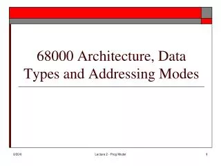
CEG3136 Computer Architecture II Module 2 – CPU Registers, Condition Codes, and Addressing Modes. Dr. Voicu Groza SITE Hall, Room 5017 562 5800 ext. 2159 Groza@SITE.uOttawa.ca. Topics of discussion. Introduction to the CPU CPU Registers CPU Condition Codes MC68HC12 Programmer’s Model

E N D
CEG3136Computer Architecture IIModule 2 – CPU Registers, Condition Codes, and Addressing Modes Dr. Voicu Groza SITE Hall, Room 5017 562 5800 ext. 2159 Groza@SITE.uOttawa.ca
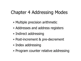
Topics of discussion • Introduction to the CPU • CPU Registers • CPU Condition Codes • MC68HC12 Programmer’s Model • Memory Addressing • Memory Architecture • Addressing Modes • Reading Assignment: Sections 4.1-4.2, 4.5-4.6
CPU Registers • Accumulators: Accumulate answers • Can also serve as source register for data operands • General-purpose registers: Hold data • Source and destination operands for data transfer instructions, • Source for ALU operations • Doubled registers: double size of registers • Combine 2 8-bit registers to form 16 bit register • Pointer Registers: address memory • Used to point to a memory address location
CPU Registers (continued) • Stack Pointer Register: dedicated to addressing memory • Used to implement subroutines • Index registers: Address memory • Add an offset value to the register contents to generate the effective address • Segment registers: Address memory • Addresses segments of memory (an offset is then used to address the memory location in the segment) • Condition Code Register: Contains flags and status • Holds condition code bits generated by the processor during execution of instructions • Some bits are used for control – ex: interrupt mask
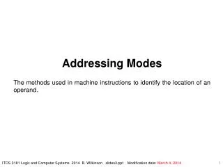
ALU MC68HC12 Block Diagram In/Out Devices SCI/SPI ADC Timer Ports D A T A B U S A7-0 = D15-8 B7-0 = D7-0 Data Path CCR S | N | Z | V | C memory LdA LdB WR RD IncPC Index register X15-0 Sequence Controller Index register Y15-0 Stack Pointer SP15-0 ADD SUB IN OUT MOV Addr | data/instructions Instruction Decoder IR xx PC 00 00 PC-Program Counter IR - Instruction Register ADDRESS BUS Control Unit Memory Address Register
S X H I N Z V C CPU12 Programmer’s Model D Accumulators A B X Index registers Y Stack Pointer SP Program Counter PC Condition Code Register (CCR) Carry =1 if unsigned carry/borrow out of/into msb OVerflow in 2’s complement Zero = 1 if every bit of ALU result is 0 Negative flag = bit 7 after ALU operation Interrupt = global interrupt mask Half-carry flag (BCD arithmetic) = 1 if carry out of bit 3->4 X = pseudo-nonmaskable interrupt mask Stop Disable = 1 => STOP = NOP, else STOP clocks
CPU 12 Programmer’s Model • Accumulators A, B, D • Two 8-bit accumulators • D is the concatenation of A and B to form 16-bit accumulator • Accumulator A is most significant byte in D • Index Registers X and Y • Primarily for indexed addressing • Are also used in some arithmetic operations • Stack Pointer • Points to the bottom of the memory stack • Need initialisation before use • Program Counter • For addressing instructions in memory • Condition Code Register • Status flags
Data types used by MC68HC12 • Bit • 5-bit signed integers (used as offset for indexed addressing) • 8-bit signed and unsigned integers • 9-bit signed integers (used as offset for indexed addressing) • 16-bit signed and unsigned integers • 16-bit effective addresses • 32-bit signed and unsigned integers (used for extended-multiply, extended division and extended multiply-and-accumulate instructions)
The Carry Bit (C) • Definition: Overflow • The result of addition or subtraction is too large or too small to be represented by number of bits available. • Carry bit set when overflow occurs during addition/subtraction of unsigned numbers • Sometimes referred to as the carry/borrow bit • Set (=1) when an overflow occurs: an addition produces a carry • a subtraction requires a borrow (also called underflow) • Can be used for multiple-byte addition or subtraction
Addition or subtraction of unsigned numbers 70!?! 204!?! Overflow
Two’s complement Overflow Bit (V) • Will the carry bit detect an overflow when numbers are treated as 2’s complement code (i.e. 2’s complement representation of signed numbers)? • Two’s complement overflow bit required • Algorithm: Two’s complement overflow occurs when: • Two operands are of the same sign AND • The sign of the result is different • Two’s complement overflow cannot occur when operands are of different signs • Note that the same hardware (and thus computer instructions) is used to add both signed and unsigned numbers
Addition and subtraction of two’s complement numbers (signed) Range of 8 bit numbers in 2’s complement representation: [-128,+127] = [-128,+128) Addition Subtraction - 1 09 1 0 0 1 0 0 1 1 - 1 09 1 0 0 1 0 0 1 1 + ( - 77) + 1 0 1 1 0 0 1 1 - ( - 77) - 1 0 1 1 0 0 1 1 - 186 1 0 1 0 0 0 1 1 0 - 32 1 1 1 1 0 0 0 0 0 Carry (C bit) V = 1 Borrow (C bit) V = 0 Overflow OK!
Sign, Zero, and Half-carry Bits • Sign Bit (N) • Set to the most significant bit of the results • Indicates sign only if result treated as a signed number (two’s complement) • Zero bit (Z) • Set (=1) when the result of the operation is zero • Half-carry bit (H) • Set (=1) when carry out of bit 3 occurs • Only used by the DAA (Decimal adjust) instruction
Example • Add the following numbers, give the results and show how the operations affect the C, V, S, and Z bits.
Bits Associated with Control • I Interrupt Mask (I) • Used to globally mask (disable) and unmask (enable) interrupts • X Interrupt Mask (X) • Used to mask (disable) and unmask (enable) for the XIRQ interrupt input • Stop Disable (S) • Allows or disallows the STOP instruction
Using the CCR bits • CCR bits set or reset by the execution of certain instructions • Conditional branch instructions can then use the bits to react to the results • Consider a BCS (branch if carry set) • Consider program that rings a bell when an overflow occurs for an unsigned addition • Load A accumulator with first byte (LDAA) • Load B accumulator with the second byte (LDAB) • Add byte in B to byte in A and store results in A (ABA) (Carry bit is set if an overflow occurs) • Branch if carry bit is set to section of the program that rings the bell (BCS) • Otherwise continue
Topics of discussion • Introduction to the CPU • CPU Registers • CPU Condition Codes • MC68HC12 Programmer’s Model • Memory Addressing • Memory Architecture • Addressing Modes
Memory Terminology • Physical Address: address applied to physical memory • Segment Address: Location of block or segment of address (smaller than full physical memory) • Offset (or Relative) Address: Calculated from the start of segment or bloc • Logical Address: logical address used by program mapped to the physical address • For example: • Segment address added to offset gives physical address • Segment number used to get address of segment from table
Memory Terminology (continued) • Effective address: address calculated by the processor • May be physical or logical address • Auto-increment and auto-decrement • Registers (for example index registers) may be incremented/decremented automatically • RAM: Random access memory - volatile • ROM: Read only memory - permanent • EEPROM (Flash Memory): permanent memory that is erasable. • Memory and I/O maps: show how all memory addresses are used • Region may contain RAM • Other region contains ROM • Some regions contain nothing
Memory Architecture – Linear addressing • Instructions specify full physical address • Motorola microprocessors use linear addressing • MC68HC12 uses 16-bit addresses • Address 64 Kbyte address space
Segmented Addressing • Address memory using segment and offset • Segment address stored in register • Offset specified in instruction • Reduces size of address in instruction • Intel 80xxx microprocessors used segmented addressing • Consider addressing in the 8086 • 16-bit segment registers • 16-bit offsets (segments occupy up to 64 Kbytes) • Shift address in segment register by 4 bits and add offset • Segments can start at any 16-byte boundary • Results in 20-bit physical address, i.e. 1 Mbyte memory address space
MC9S12DG256 Paging Although a 16 bit address is used within the HCS12 MCU, it is possible to expand memory using the Program Page Index Register (PPAGE) 6 bits are used in PPAGE used to access up to 64 – 16Kbyte pages of external memory The pages are accessed at addresses $8000-$BFFF within the 64kByte memory map of the MCU Use of PPAGE is restricted to certain instructions, see CALL and RTC This allows expansion to an additional 1Mbyte memory Similar to segmentation 25
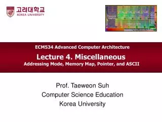
$ 0000 $ 1000 $ 2000 $ 3000 $ 4000 $ 5000 $ 6000 $ 7000 $ 8000 $ 9000 $ A 000 $ B 000 $ C 000 $ D 000 $ E 000 $ F 000 MC9S12DG256 Memory Map • Motorola products use linear addressing • In single chip mode (no external addressing), addresses: • On-chip registers to I/O interfaces ($0000 to $03FF) • 3 KBytes EEPROM ($0400 to $0FFF) • 12 KByte RAM ($1000 to $30FF) • $3C00 to $3FFF is used by the D-Bug12 Monitor • 48 KByte EEPROM Memory ($4000 to $FFFF) RAM 0000 I / O Registers 0400 FLASH D - Bug 12 EEPROM 0FFF
$0000 $ 10 00 $ 2 0 00 $ 30 00 NO $ 4 0 00 MEMORY $ 5 0 00 !!! $ 6 0 00 $ 7 0 00 $ 8 0 00 $ 9 0 00 $ A 0 00 EEPROM $ B 0 00 Dbug $ C 0 00 12 $ D 0 00 $ E 0 00 $ F 0 00 MC69HC912B32 Memory Map
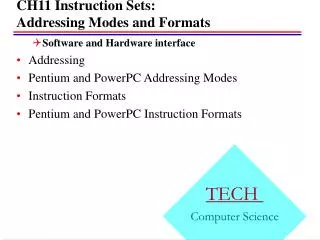
Addressing Modes • Inherent (CPU Register) Addressing • Operands reference internal registers • Also called inherent addressing (Motorola) • Immediate Addressing • Operand is constant and immediately follows the opcode • Direct Addressing • The Operand that follows the opcode contains the memory address • Indexed addressing • Finds the data address using an index (an offset) • Indirect Addressing • Instruction specifies where the address of the data is located • Relative Addressing • Add offset to current value of the PC • Stack Addressing • Addressing memory reserved for temporary storage used on a last-in first-out basis. (the stack).
Notation used in Comments • Register Name: Indicates a register and its contents • Example: A refers to the contents of accumulator A • → (->) Right arrow indicates data transfer operation (<-> indicates an exchange of data) • Example: A -> B indicates the contents of A are transferred (copied) to B • (…) Contents of a memory location • Example: ($1234) -> B indicates that the contents of memory location $1234 are transferred to B • ((…)) Indirect addressing – inner parentheses specifies a memory address that contains the data address • Example: A ->(($1234)) indicates that the contents of A are transferred to a memory location is found in $1234:$1235.
Inherent Addressing (Register Addressing) • All data for instructions are in the CPU • Instructions with inherent addressing • Are among the fastest to execute • Coded with the least amount of bits • Also called Register Addressing or Implied Addressing 0000 1806 1 aba ; A+B -> A 0002 08 2 inx ; X+1 -> X 0003 B781 3 exg a,b ; A <-> B
Memory SP B A X Y 86 40 Immediate Addressing An argument is contained in the byte(s) immediately following the opcode. The number of bytes following the opcode matches the size of the register or memory location being operated on. • The # symbol indicates immediate addressing • It is easy to forget the # The 8-bit contents of the selected memory location are moving, as specified by the instruction, to accumulator A The effective address is the address of the byte following the instruction. Immediate Addressing Examples 0800 8640 1 ldaa #64 ; Decimal 64 -> A 0802 8664 2 ldaa #$64 ; Hexadecimal 64 -> A 0804 CE1234 3 ldx #$1234 ; Hexadecimal 1234 -> X
SP B A X Y Memory 0000 0001 0002 0003 0004 0005 0807 0808 0809 080A 080B 080C The 8-bit contents of the selected memory location are moving, as specified by the instruction, to the accumulator A. 96 The 8-bit contents (07) of the last byte of the instruction represents the address of this memory location Two byte instruction 04 Direct Memory Addressing • Instruction contains the data address • Single-level addressing The low-order byte of the operand address is contained in a single byte following the opcode, and the high-order byte of the address is assumed to be $00. Addresses $00–$FF are thus accessed directly, using 2-byte instructions. In many microprocessors, this 256-byte area is reserved for frequently referenced data; the following example refers to an HC12 I/O device. Example: ldaa 4 ;A <- m[4]
CPU12 Direct Memory Addressing • CPU12 defines two modes of direct memory addressing • Direct Addressing – uses 8-bit memory address ($0000 to $00FF, i.e. 0 to 255) • Extended Addressing – uses 16-bit address to address all 64 K addresses ; Direct Addressing 0800 9664 1 ldaa 100 ; ($0064) -> A, i.e., PORTAD-> A 0802 5BC2 2 stab $FF ; B -> ($00FF) 0804 DE0A 3 ldx 10 ; ($000A:000B) -> X ; Extended Addressing 0806 B61234 1 ldaa $1234 ; ($1234) -> A 0809 FC1234 2 ldd $1234 ; ($1234:1235) -> D 080C 7EC000 3 stx $c000 ; X -> ($C000:C001)
offset base base offset Indexed addressing Indexed addressingIndex Register = offset Based addressingIndex Register = base • Calculates an effective address by summing a base address to an offset (index)
HCS12 Indexed Addressing = (called Based Addressing in other systems)
HC12 Indexed AddressingUsing Constant Offset • Effective address = offset + contents of index register • Offset can be 5-, 9-, or 16-bit offset • Index register can be X, Y, SP, or PC • Index register content remains unchanged! 0800 A600 1 ldaa ,x ; (X+0) 5-bit offset -> A 0802 A600 2 ldaa 0,x ; (X+0) 5-bit offset -> A 0804 A6E040 3 ldaa 64,x ; (X+64) 9-bit offset -> A 0807 A6E9C0 4 ldaa -64,y ; (Y-64) 9-bit offset -> A 080A 6A9F 5 staa -1,SP ; A -> (SP-1) 5-bit offset 080C A6FA1388 6 ldaa 5000,PC ; (PC+5000) 16-bit offset -> A
Indexed Addressing with Automatic Incrementing and Decrementing • Use + and – in instruction to include automatic incrementing and decrementing of index register • Position of +/- indicates to modify index register before (pre) or after (post) the data value was accessed • Offset value (-8,+8) is added/subtracted to/from index register (index register is changed) 1 ; Pre-decrement 0900 A629 2 ldaa 7,-X ; X-7 -> X, (X) -> A 3 ; Post-decrement 0902 A63E 4 ldaa 2,X- ; (X) -> A, X-2 -> X 5 ; Pre-increment 0904 A620 6 ldaa 1,+X ; X+1 -> X, (X) -> A 7 ; Post-increment 0906 A630 8 ldaa 1,X+ ; (X) -> A, X+1 -> X
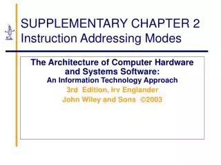
Memory The 8-bit contents of the selected memory location ($09B5) is moved, as specified by the instruction, to the accumulator A. 09B5 09B6 09B7 The content of index register X added to the content of the (offset) accumulator B gives the address of this memory location 09B8 09B9 09BA 09BB Accumulator Offset Indexed Addressing An offset contained in the accumulator (A, B, or D) pointed to by the instruction is added to the value contained in an index register (X, Y, SP or PC). The sum is the effective address; the registers remain unchanged. This addressing mode allows referencing any memory location in the 64-KB address space. Example: LDAA B,X ;A <- m[(B)+(X)] A,B AA $B6 09B0 A6 X $0900 09B1 E5 09B2 Y 09B3 SP 09B4 EA=(B)+(X) effective address $09B6 AA 09B0 A6E5 1 ldaa B,X ; (X+B) -> A 09B2 E6EC 2 ldab A,Y ; (Y+A) -> B 09B4 EDE6 3 ldy D,X ; (X+D:X+D+1) -> Y
Indirect Addressing • Two level addressing mechanism • First level provided by instruction gives address of memory containing an address • Second level is the address that specifies where the data is located • Register Indirect: Register contains the data address • Register Indirect with auto-increment or auto-decrement: register automatically incremented/decremented • Memory Indirect: Data address found in memory
Register Indirect Addressing • Also called pointer register addressing • Instruction contains address of register holding the data address • Data address can be calculated at run time • Registers may also be incremented or decremented automatically
HCS12 Indexed-Indirect Addressing Modes • Provides memoryindexed-indirectaddressing using • a constant offset • Instruction provides a 16-bit offset • accumulator offset • D register contains the 16-bit offset • 16-bit offset is added to the index register to obtain the effective address to the data address • The address found at the effective address is then used to address the data
Memory 12 09B5 34 09B6 09B7 09B8 09B9 09 09BA B5 09BB HCS12Accumulator D IndexedIndirect Addressing Example: stx [D,Y] ;X <- m{m[(D)+(Y)]} 2. The 16-bit contents of register X are moved in memory at the address given by the pointer stored at addr $09B5 D 0800 X 1234 Y 01BA SP SP 1.The content of index register Y added to the content of the offset register D gives the address of this memory location that stores a pointer EA=(D)+(Y) 09BA
HCS12 Indirect Indexed Instructions • Instruction Format • Operation [Offset, Index_register] • 16-bit Offset • Operation [D,Index_register] • Index_register can be X, Y, SP, PC ;16-bit Constant Indexed-Indirect Addressing 0000 CE5000 1 ldx #$5000 ; $5000 -> X, Initialize X 0003 A6E30064 2 ldaa [$64,X] ; (($5064)) -> A 0007 6AE3FFFF 3 staa [-1,X] ; A -> (($4fff)) ;Indexed-Indirect Addressing using Accumulator D 0000 CE5000 1 ldx #$5000 ; $5000 -> X, initialize X 0003 CC0064 2 ldd #$064 ; $0064 -> D, initialize D 0006 EFE7 3 lds [D,X] ; (($5064)) -> SP
Relative Addressing • Calculate the effective address by adding offset to the current value of the PC • Used mostly for branching instructions • Normally offset is calculated from the address of the next op-code
HCS12 Relative Addressing • Short branching instructions: 8-bit offsets (offset ranges between -128 to +127) • Long branching instructions: 16-bit offsets (offset ranges between -32,768 to +32,767) • Loop primitive instructions that use 9-bit offsets (range between -256 to +255) 0000 2002 1 THERE: bra WHERE ; Forward branch 0002 A7 2 nop 0003 A7 3 nop 0004 22FA 4 WHERE: bhi THERE ; Conditional branch back 0006 18260256 5 lbne LONG_BRANCH 000A 6 DS 256 ; Simulate instructions 7 LONG_BRANCH: 0260 A7 8 nop