Download
1 / 228
2.28k likes | 2.28k Views
ITSCNC offer fadal safety section manual covers information for VMCs EMC, 5, 10, 15, 15XT, 2016L, and 8030; Rotary Tables and V300 (400) MM; and VH5C Indexer.<br>

E N D
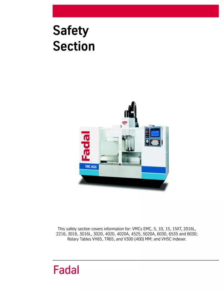
Safety Section This safety section covers information for: VMCs EMC, 5, 10, 15, 15XT, 2016L, 2216, 3016, 3016L, 3020, 4020, 4020A, 4525, 5020A, 6030, 6535 and 8030; Rotary Tables VH65, TR65, and V300 (400) MM; and VH5C Indexer. Fadal
SAFETY SECTION Fadal TABLE OF CONTENTS TABLE OF CONTENTS............................................................................................................................... 1 MODIFICATIONS, ALTERATIONS, AND CHANGES.............................................................................................. 3 SAFETY WARNINGS ...................................................................................................................................... 4 GENERAL..................................................................................................................................................... 7 WARNINGS AND CAUTIONS ........................................................................................................................... 8 PICTORIALS................................................................................................................................................. 8 POTENTIAL HAZARDS TO PERSONNEL............................................................................................................ 8 PHYSICAL ENVIRONMENT AND OPERATING CONDITIONS (CE SPECIFICATIONS).................................................. 8 ELECTRIC SHOCK ......................................................................................................................................... 9 SHARP EDGES ON CUTTING TOOLS................................................................................................................ 9 ROTATING CUTTING TOOLS........................................................................................................................... 9 NOISE ......................................................................................................................................................... 10 NOISE (CE COMPLIANCE)............................................................................................................................... 10 COMPRESSED AIR (CE COMPLIANCE).............................................................................................................. 11 ADDITIONAL SAFETY PRECAUTIONS............................................................................................................... 12 SAFETY LABELS........................................................................................................................................ 14 LBL-0123 .................................................................................................................................................... 14 LBL-0129 .................................................................................................................................................... 15 LBL-0158 .................................................................................................................................................... 15 LBL-0127 .................................................................................................................................................... 15 LBL-0130 .................................................................................................................................................... 16 LBL-0163 .................................................................................................................................................... 16 LBL-0126 .................................................................................................................................................... 17 LBL-0128 .................................................................................................................................................... 18 LBL-0125 .................................................................................................................................................... 19 LBL-0235 .................................................................................................................................................... 20 LBL-0131 .................................................................................................................................................... 21 LBL-0263 .................................................................................................................................................... 21 LBL-0187 .................................................................................................................................................... 22 LBL-0234 .................................................................................................................................................... 22 LBL-0124 .................................................................................................................................................... 23 LBL-0040 .................................................................................................................................................... 24 LBL-0036 .................................................................................................................................................... 24 SAFETY LABEL LOCATIONS..................................................................................................................... 25 4020S......................................................................................................................................................... 25 5020A, 4020A, 4020, 3016L, 2216, 2016L, 15, 15XT...................................................................................... 27 6030, 8030.................................................................................................................................................. 29 4525, 3020.................................................................................................................................................. 33 August 2001 SS-i Safety Section
SAFETY SECTION Fadal CE SAFETY LABELS................................................................................................................................... 37 LBL-0431 small (CE) LBL-0434 large (CE) ........................................................................................................ 37 LBL-0432 (CE).............................................................................................................................................. 37 LBl-0132 (CE)............................................................................................................................................... 38 LBL-0435 (CE).............................................................................................................................................. 38 LBL-0460 (CE).............................................................................................................................................. 39 LBL-0430 (CE).............................................................................................................................................. 39 LBL-0436 (CE).............................................................................................................................................. 40 LBL-0433 (CE).............................................................................................................................................. 40 LBL-0443 (CE).............................................................................................................................................. 41 PROHIBITIONS.......................................................................................................................................... 42 LBL-0441 (CE).............................................................................................................................................. 42 REQUIRED ACTIONS................................................................................................................................. 43 LBL-0439 (CE).............................................................................................................................................. 43 LBL-0440 (CE).............................................................................................................................................. 43 LBL-0442 (CE).............................................................................................................................................. 44 LBL-0438 small (CE) LBL-0437 large (CE) ........................................................................................................ 44 CE SAFETY LABEL LIST AND LOCATION................................................................................................ 45 Safety Section SS-ii August 2001
SAFETY SECTION Fadal Corporate Office voice (818) 407-1400fax (818) 407-0020 Service / Parts voice (818) 727-2100fax (818) 407-1004 Programming Support voice (818) 727-2100fax (818) 407-0061 support@fadal.com 20701 Plummer Street Chatsworth California 91311 U.S.A. The information in this document is reviewed regularly and any necessary changes will be incorporated in the next revision. We welcome any suggestions for improvement. Material is subject to change without notice. This manual is for the exclusive use of Fadal Customers and Distributors. The reproduction, transmission or use of this document or its contents is not permitted without the expressed written permission of Fadal Machining Centers. © Copyright 2001 Fadal Machining Centers. Safety Section SS-2 May 2002
SAFETY SECTION Fadal MODIFICATIONS, ALTERATIONS, AND CHANGES Do not modify or alter this equipment without the written approval of Fadal Machining Centers. Unauthorized changes may lead to hazardous conditions. Address any questions to Fadal’s Service Department. May 2002 SS-3 Safety Section
SAFETY SECTION Fadal SAFETY WARNINGS 1. WARNING! WEAR ANSI or CE APPROVED SAFETY GLASSES AT ALL TIMES. Everyday glasses are not designed for protection. Only ANSI or CE approved safety glasses have impact resistant lenses. Hearing protection must be worn when operations exceed 90 (85 CE) decibels. 2. KEEP DOORS CLOSED WHILE MACHINING. 3. WEAR PROPER APPAREL. Do not wear loose clothing, gloves, neckties, rings, bracelets, or other jewelry that might get caught in moving parts or areas of potential electric shock. Non-slip footwear is recommended. 4. CONTAIN LONG HAIR. Tie long hair back and wear protective hair covering to contain long hair. 5. USE A NIOSH OR CE APPROVED DUST MASK OR RESPIRATOR. Protection is recommended when cutting operations are dusty, or exceed the permis- sible exposure limit. 6. KEEP WORK AREA CLEAN. Good housekeeping practices encourage safety. 7. Read SPINDLE, MANUALLY LOADING & UNLOADING A HOLDER in the Operator’s Manual. 8. DO NOT OPERATE THE MACHINE UNDER THE INFLUENCE OF DRUGS OR ALCOHOL, PRESCRIBED OR OTHERWISE. 9. READ THE SAFETY WARNINGS SUPPLIED WITH ALL TOOLING. 10.MAINTAIN TOOLS WITH CARE. Keep tools sharp and clean for best perfor- mance and to reduce the risk of injury. Follow instructions for lubrication and for changing accessories. 11.REMOVE ADJUSTING KEYS AND WRENCHES. Always check that keys and wrenches are removed from tools and tooling before starting the machine. 12.DO NOT EXCEED THE MANUFACTURER’S RECOMMENDED MAXIMUM RPM FOR THE TOOL. When tools are placed in the spindle, verify the current RPM commanded in the control before starting the spindle. 13.SECURE TOOLS PROPERLY IN THEIR HOLDERS. 14.SECURE WORK. Use common machining practices for holding (fixturing) material to be machined. 15.REMOVE ALL TOOLS FROM THE SPINDLE AND TOOL CHANGER before ser- vicing and changing accessories such as tooling, fixtures, indexers, the tail stock of a fourth axis and any fourth axis or fourth-fifth axis combination, etc. 16.ALWAYS DEBUG A NEW PROGRAM before running it in the AUTO mode. (See DEBUG PROGRAM in the User’s Manual.) 17.The machine tool MUST be connected to a grounded, metal, permanent wiring system, or to a system having an equipment-grounding conductor. Safety Section SS-4 May 2002
SAFETY SECTION Fadal 18.DO NOT OPERATE THE MACHINE IN AN UNSAFE ENVIRONMENT. Do not use the machine in damp or wet locations, or expose to rain. Keep the work area well lighted. 19.DO NOT FORCE TOOL. Tools are designed to perform properly and safely at proper rates. Keep tools sharp. 20.USE THE CORRECT TOOL. Do not attempt to use tools or attachments to perform a job for which they were not designed. 21.DON’T OVERREACH. Keep proper footing and balance at all times. Use a steady object for support when reaching over the machine. 22.REDUCE THE RISK OF UNINTENTIONAL STARTING. Power off the machine at the main disconnect switch and use the proper lockout/tagout proce- dures while working within the chip enclosure, or when there is potential for a release of energy. 23.POWER OFF THE MACHINE AT THE MAIN DISCONNECT SWITCH AND LOCK OUT WHEN WORKING INSIDE ANY OF THE ELECTRONIC CABINETS. 24.USE RECOMMENDED ACCESSORIES. Refer to the User’s Manual for FADAL recommended accessories. Unapproved accessories increase the risk of injury. 25.NEVER STAND ON OR IN THE MACHINE. Besides the risk of slipping or fall- ing, serious injury could occur if a tool is unintentionally contacted. 26.CHECK FOR DAMAGED PARTS. Always check all parts for binding, break- age, and any other condition that will affect the proper operation of the machine and/or increase the risk of injury. Damaged or missing parts must be repaired or replaced BEFORE operating the machine. 27.NEVER LEAVE THE MACHINE UNATTENDED. Turn the power off to the machine when leaving the machine unattended. Never leave the machine until it comes to a complete stop. 28.DO NOT DISCONNECT THE FRONT DOOR SAFETY SWITCHES. 29.)WIPE UP SPILLS. Immediately cover with absorbent material and wipe up coolant and oil spills around the machine. Correct the cause of the leakage to prevent any hazards. 30.ELECTRICAL INSTALLATION OF THE MACHINE MUST BE DONE BY A QUAL- IFIED ELECTRICIAN. 31.ONLY FADAL OR FADAL DISTRIBUTOR FACTORY AUTHORIZED INDIVIDU- ALS MAY INSTALL THE MACHINE. 32.USE PROPER SAFETY GLOVES WHEN HANDLING SHARP OR JAGGED EDGES. Do not wear gloves around rotating machinery. May 2002 SS-5 Safety Section
SAFETY SECTION Fadal 33.DO NOT USE AIR HOSES TO BLOW CHIPS OFF YOUR BODY OR CLOTHES. Serious injury to your eyes, hearing, and skin could result. Do not blow towards others. Safety Section SS-6 May 2002
SAFETY SECTION Fadal GENERAL A carelessly or improperly operated VMC can cause serious injury or death as well as damage or destruction of equipment. The emergency and safety procedures in this manual are to help users operate the VMC in a safe manner. The warnings in this manual follow accepted industry safety practices. Tasks involving toxic materials must be reviewed and approved by an industrial hygienist or safety engineer. Fadal has no control over the applications the operator may use the VMC for and is not responsible for injuries or equipment damage. Read and understand the User’s Manual. The safe use and disposal of all hazardous materials processed or used by the VMC is the responsibility of the user. All safety warnings and procedures must be followed. It is the sole responsibility of the user to comply with all local, state, national (Federal), and international and environmental safety laws and regulations applicable to the VMC and its use. May 2002 SS-7 Safety Section
SAFETY SECTION Fadal WARNINGS AND CAUTIONS This manual contains information that will assist qualified operators and maintenance personnel. Unqualified operators should never attempt to operate or perform maintenance on the VMC. PICTORIALS Pictorials are used within warnings to rapidly communicate a hazard to the reader. The pictorials and their meaning are given in this section. A diagram of the locations and types of warnings that are physically attached to, or engraved on, the VMC is also included. POTENTIAL HAZARDS TO PERSONNEL The most serious potential hazards associated with the VMC are: • electric shock • sharp edges on cutting tools • rotating cutting tools • noise • compressed air PHYSICAL ENVIRONMENT AND OPERATING CONDITIONS (CE SPECIFICATIONS) FADAL VMCs meet or exceed the environmental requirements stated in EN 60204-1:1992 section 4.4. Electromagnetic Compatibility meets or exceeds the levels specified by EN 50081-2:1993 and EN 50082-2:1995. Ambient air temperature conforms as specified in EN60204-1:1992 section 4.4.2 (+5 deg C to +40 deg C). Humidity conforms as specified in EN60204-1:1992 section 4.4.3 (relative humidity 30% to 95% non-condensing). Altitude conforms as specified in EN60204-1:1992 section 4.4.4 (maximum altitude without derating exceeds 1000 meters above sea level). Contaminants conform as specified in EN60204-1:1992 section 4.4.5. Equipment is not intended for use in a corrosive atmosphere. Equipment that will be used in an environment with excessive amounts of fine conductive particulate matter (e.g. graphite) must be ordered with the graphite restraint package. Safety Section SS-8 May 2002
SAFETY SECTION Fadal ELECTRIC SHOCK The VMC has numerous subsystems powered by high voltage electricity. This electricity is not a hazard during most operations, however certain maintenance operations conducted by qualified individuals may require the defeat of interlocks so that power may be maintained during diagnostics or adjustments tasks. Under no circumstances should the operator defeat any interlock. Read all applicable manuals and follow their warnings to prevent accidental electric shock. Operators must never remove shields or panels, nor should operators bypass or otherwise disable interlocks. SHARP EDGES ON CUTTING TOOLS Cutting tools have sharp edges that could lead to a serious cut. The tools used on the VMC are stored in a tool tray when not being used. Under most circumstances they pose no threat to operator or maintenance personnel. It is possible for personnel to come into contact with stationary cutting tools during job setup or when replacing cutting tools for any reason. Extreme care must be taken to avoid coming into contact with the sharp edges on cutting tools. ROTATING CUTTING TOOLS Rotating cutting tools used by the VMC create potential hazards of entanglement. A cutting hazard is also possible if the operator comes into contact with rotating cutting tools. The Polycarbonate shield is equipped with an interlock to prevent the VMC from operating when the shield is opened. Under no circumstances should operators disable or remove the interlocks. If the interlock is not functioning properly, qualified maintenance personnel should be notified and the VMC must not be used until it is functioning properly. Prior to starting any job, the operator on the VMC should inspect all of the cutting tools being used to ensure they are in good condition and free of defects such as cracks. The operator should also insure that only the appropriate cutting tools for the material being machined are present. Using the wrong tool or using a damaged tool could result in the failure of the tool or material being machined. Failure of either could lead to pieces of either the tool or the material being ejected at extremely high speed. Ejection of either could lead to serious injury or death to personnel in the vicinity. Major equipment damage could also be sustained. May 2002 SS-9 Safety Section
SAFETY SECTION Fadal NOISE Exposure to occupational hazardous noise or prolonged exposure to noise above 90 decibels may cause permanent hearing damage. The amount of noise the VMC produces varies by the type of material, speed of the cut, and several other factors. To prevent loss of hearing from the noise of an operating VMC, hearing protection must always be worn by personnel exposed to noise above 90 decibels or above. The level of protection required may vary because of variation in the amount of noise being produced by the VMC. To insure adequate hearing protection is attained, compliance with OSHA standards is required. Consult a qualified industrial hygienist or safety engineer to insure adequate protection prior to operating the VMC. NOISE (CE COMPLIANCE) Exposure to occupational hazardous noise or prolonged exposure to noise above 85 decibels may cause permanent hearing damage. The amount of noise the VMC produces varies by the type of material, speed of the cut, and several other factors. To prevent loss of hearing from the noise of an operating VMC, hearing protection must always be worn by personnel exposed to noise above 85 decibels or above. The level of protection required may vary because of variation in the amount of noise being produced by the VMC. To insure adequate hearing protection is attained, compliance with CE standards is required. Consult a qualified industrial hygienist or safety engineer to insure adequate protection prior to operating the VMC. Continuous equivalent A-weighted sound pressure at workstation is 77dB(A) or less when tested according to Annex D of prEN 12417. The figures quoted are emission levels and are not necessarily safe working levels. While there is a correlation between the emission and exposure levels, this cannot be used reliably to determine whether or not further precautions are required. Factors that influence the actual level of exposure of the workforce include characteristics of the work room, the other sources of noise, etc. i.e., the number of machines and other adjacent processes. Also the permissible exposure level can vary from country to country. This information, however, will enable the user of the machine to make a better evaluation of the hazard and risk. Safety Section SS-10 May 2002
SAFETY SECTION Fadal COMPRESSED AIR (CE COMPLIANCE) Compressed air poses a potential hazard from flying debris. Under normal conditions the compressed air may not present a hazard to the operator. Failure of any component of a compressed air system may cause parts to be ejected at high speed. Operators and maintenance personnel must always wear eye protection that meets OSHA standards and ANSI standard Z87.1 (or CE standards) when working on systems that use compressed air. The operator may also use their shop’s compressed air to remove debris from material being machined. If shop air is used for this purpose, it must be done in accordance with OSHA or CE standards. Alternative means of debris removal, such as debris rakes, should be considered. UNDER NO CIRCUMSTANCES SHOULD THE OPERATOR ATTEMPT TO REMOVE DEBRIS WHILE THE VMC IS RUNNING. Consult a qualified industrial hygienist or safety engineer to insure debris removal is accomplished in a safe manner and in a manner that complies with local, state, national (Federal), and international regulations. May 2002 SS-11 Safety Section
SAFETY SECTION Fadal ADDITIONAL SAFETY PRECAUTIONS Compliance with the following safety practices is required to safely operate the VMC: 1. Never work alone on live electrical circuits. Another person qualified to turn off power to the VMC must be present when voltage is 600 or over. That person must also know CPR (cardiopulmonary resuscitation) and company emergency procedures. 2. Never wear jewelry or loose fitting clothing while working on the VMC. Long hair should be secured and under a cap. 3. .Wear eye protection when operating or maintaining this machine. 4. Never operate this machine without all guards, safety shields, and inter- locks in place and functioning properly. 5. Report any unsafe conditions to the supervisor immediately. Do not operate this machine until the unsafe condition has been resolved. If the operator is not familiar with a condition, consult an industrial hygienist or safety engi- neer for approval prior to proceeding. 6. Comply with all local, state, national (Federal), and international (CE) regu- lations pertaining to the handling, processing or disposal of hazardous materials used in conjunction with VMC operations. 7. Do not leave electrical cords where they may be tripped over. Secure all electrical cords and compressed air lines connected to the VMC. 8. Keep a UL or CE approved fire extinguisher close to the VMC and make sure all personnel know the location of the fire extinguisher. 9. Do not turn the VMC on or try to operate it if there are explosive or flamma- ble gases present. 10.Do not install substitute parts or modify the VMC without consulting a safety engineer. Contact FADAL or your local distributor for authorized repair parts and service. 11.The Polycarbonate viewing panels are an integral part of the safety enclo- sure for the VMC. They must be inspected at least monthly for any signs of reduced effectiveness (such as cracking or crazing) and replaced immedi- ately if such signs or other indications of reduced effectiveness are noticed. Furthermore, tests have indicated that coolants can reduce the effective- ness of the panels over a period of time, therefore the panels should be replaced, regardless of condition, at least every two years. Safety Section SS-12 May 2002
SAFETY SECTION Fadal 12.The Polycarbonate shield is equipped with an interlock to prevent the VMC from operating when the shield is opened. Under no circumstances should the operator disable or remove the interlocks. If power is lost to the VMC, the spindle will free wheel for 30 seconds. Under no circumstances should the operator open the Polycarbonate shield before the spindle stops rotat- ing completely. 13.The machine is not intended for use with flammable or harmful sub- stances. 14.Take appropriate additional safety precautions and measures when work- ing with magnesium, wood, or other combustible materials. 15.Dust removal equipment is needed when working with dust-producing materials or procedures. 16.Due to danger of slips or falls on a wet or oily surface, table and enclosure floor should be clean and dry before using them for maintenance access. 17.Do not enter enclosure area unless machine is off and power is locked out. May 2002 SS-13 Safety Section
SAFETY SECTION Fadal SAFETY LABELS LBL-0123 Safety Section SS-14 May 2002
SAFETY SECTION Fadal LBL-0129 LBL-0158 LBL-0127 May 2002 SS-15 Safety Section
SAFETY SECTION Fadal LBL-0130 LBL-0163 Safety Section SS-16 May 2002
SAFETY SECTION Fadal LBL-0126 May 2002 SS-17 Safety Section
SAFETY SECTION Fadal LBL-0128 Safety Section SS-18 May 2002
SAFETY SECTION Fadal LBL-0125 May 2002 SS-19 Safety Section
SAFETY SECTION Fadal LBL-0235 Safety Section SS-20 May 2002
SAFETY SECTION Fadal LBL-0131 LBL-0263 May 2002 SS-21 Safety Section
SAFETY SECTION Fadal LBL-0187 LBL-0234 Safety Section SS-22 May 2002
SAFETY SECTION Fadal LBL-0124 May 2002 SS-23 Safety Section
SAFETY SECTION Fadal LBL-0040 LBL-0036 Safety Section SS-24 May 2002
SAFETY SECTION Fadal SAFETY LABEL LOCATIONS 4020S LBL-0129 LBL-0234 LBL-0123 LBL-0234 LBL-0123 LBL-0163 May 2002 SS-25 Safety Section
SAFETY SECTION Fadal LBL-0235 LBL-0125 LBL-0128 LBL-0234 Safety Section SS-26 May 2002
SAFETY SECTION Fadal 5020a, 4020a,4020, 3016L, 2216, 2016L, 15, 15xt, EMC LBL-0128 LBL-0263 LBL-0126 LBL-0263 LBL-0128 LBL-0235 May 2002 SS-27 Safety Section
SAFETY SECTION Fadal LBL-0125 LBL-0125 LBL-0235 LBL-0127 Safety Section SS-28 May 2002
SAFETY SECTION Fadal 6030, 8030 LBL-0123 LBL-0128 LBL-0263 LBL-0235 LBL-0128 LBL-0263 May 2002 SS-29 Safety Section
SAFETY SECTION Fadal LBL-0235 LBL-0126 LBL-0129 LBL-0124 Safety Section SS-30 May 2002
SAFETY SECTION Fadal LBL-0235 LBL-0125 LBL-0123 LBL-0163 LBL-0128 May 2002 SS-31 Safety Section
SAFETY SECTION Fadal LBL-0128 LBL-0263 LBL-0235 LBL-0263 LBL-0128 LBL-0235 Safety Section SS-32 May 2002
SAFETY SECTION Fadal 6535, 4525, 3020 LBL-0126 LBL-0036 LBL-0123 May 2002 SS-33 Safety Section
SAFETY SECTION Fadal LBL-0128 LBL-0123 LBL-0128 LBL-0263 LBL-0126 Safety Section SS-34 May 2002
SAFETY SECTION Fadal LBL-0128 LBL-0263 LBL-0036 LBL-0235 LBL-0125 May 2002 SS-35 Safety Section
SAFETY SECTION Fadal LBL-0235 LBL-0125 Safety Section SS-36 May 2002
SAFETY SECTION Fadal CE SAFETY LABELS LBL-0431 small (CE) LBL-0434 large (CE) Cutting of Fingers or Hand / Rotating Cutter Cutting tools can seriously injure. Never place any part of your body near rotating tools. Do not operate this machine unless the doors are closed and the door interlocks are working. LBL-0432 (CE) Hand Entanglement / Belt Drive Rotating pulleys and belts can seriously injure. Never place any part of your body near rotating or moving parts. Always insure that guards are in place before operating this machine. May 2002 SS-37 Safety Section
SAFETY SECTION Fadal LBl-0132 (CE) Electric Shock / Electrocution Hazardous voltages in this enclosure can kill. Do not operate with the door open. Servicing should be done by qualified personnel only. Lockout the power before servicing. LBL-0435 (CE) Flying Debris and Loud Noise Flying objects from this machine may injure. Always wear safety glasses when operating this machine. Do not operate this machine with the doors open or the enclosures removed. Also, noise from this machine can damage hearing. Always wear ear protection when operating this machine. Safety Section SS-38 May 2002
SAFETY SECTION Fadal LBL-0460 (CE) Flying Debris Flying debris and compressed air can cause eye injuries. Do not perform maintenance on pressurized systems. Disconnect the air source before performing maintenance. Always wear eye protection when performing maintenance on compressed air systems. LBL-0430 (CE) Skin Puncture / Pressurized Air Compressed air can seriously injure. Do not perform maintenance on pressurized systems. Disconnect air source before performing maintenance. Always wear eye protection when performing maintenance on compressed air systems. May 2002 SS-39 Safety Section
SAFETY SECTION Fadal LBL-0436 (CE) Leg or Body Entanglement / Auger Auger can serious injure or kill. Keep body parts out of the auger system at all times. Turn off the machine and lockout the power before doing maintenance inside the enclosure. LBL-0433 (CE) Hand Crush / Moving Parts Automatic pallet changer door will crush hands. Stand clear when the door is closing. Safety Section SS-40 May 2002
SAFETY SECTION Fadal LBL-0443 (CE) Hand Crush / Force from Side Automatic pallet changer can crush hands. Do not place hands or any part of the body in the path of a moving pallet. May 2002 SS-41 Safety Section
SAFETY SECTION Fadal PROHIBITIONS LBL-0441 (CE) Do Not Operate with Guard Removed Do not operate this machine with the doors open or the guards removed. Moving machinery and rotating cutters can seriously injure or kill. Safety Section SS-42 May 2002
SAFETY SECTION Fadal REQUIRED ACTIONS LBL-0439 (CE) Wear Eye Protection Flying objects may injure. Always wear safety glasses when operating this machine. LBL-0440 (CE) Wear Ear Protection Noise from this machine can damage hearing. Always wear ear protection when operating this machine. May 2002 SS-43 Safety Section
SAFETY SECTION Fadal LBL-0442 (CE) Consult Operator's Manual Read and understand the Operator's Manual before operating this machine. This machine must be operated by qualified personnel only, LBL-0438 small (CE) LBL-0437 large (CE) Lockout Electrical Power Whenever servicing the machine, turn the machine off and lockout the power. Turn off the machine and lockout the power before working in this cabinet. Safety Section SS-44 May 2002
SAFETY SECTION Fadal CE SAFETY LABEL LIST AND LOCATION Location Domestic or old Labels CE Labels ATC Slide Arm Plate LBL-0129 LBL-0432 (1009B-ISO), LBL-0438 (6011B-ISO) Spindle Belt Guide (inside spindle cover) LBL-0129 LBL-0432 (1009B-ISO), LBL-0438 (6011B-ISO) Front by Pendant LBL-0123, LBL-0163 LBL-0435 (3002A-ISO), LBL-0439 (6040A-ISO), LBL-0440 (6041A-ISO), LBL-0442 (6126A-ISO) Tool Turret Cover LBL-0136 LBL-0136 (revised) Tool Changer Cover LBL-0127 LBL-0434 (1007A-ISO) Head (Spindle) Cover LBL-0435 (3002A-ISO), LBL-0439 (6040A-ISO), LBL-0440 (6041A-ISO) LBL-0137,-0138, or -0139 (revised) LBL-0130 LBL-0137,-0138, or -0139 Right Front Door LBL-0124 LBL-0140 LBL-0431 (1007B-ISO), LBL-0441 (6060B-ISO) (LBL-0140 deleted after doors locked) On Control, Transformer, and Pendant Cabinet Doors LBL-0128, LBL-0131 --- LBL-0131 (6010A-ISO) Inside of Control, Transformer, and Pendant Cabinets LBL-0125 LBL-0235 LBL-0131 (6010A-ISO), LBL-0437 (6011A-ISO) (B size labels used in Slant Control cabinet - LBL- 0461, LBL-0438) Grounding Labels LBL-0133 (chassis ground) LBL-0186 (Protective Earth input) LBL-0133, LBL-0186 (same) Flood, Mist, RS-232 Outlets LBL-0192, LBL-0188, LBL-0189 LBL-0192, LBL-0188, LBL-0189 (same) On Chiller Cabinet LBL-0300 LBL-0300 (same, 3 languages) Chiller Outlets LBL-0191, LBL-0190 LBL-0191, LBL-0190 (same) CNC Power Button LBL-0038 LBL-0038 (same) Air Regulator LBL-0126 LBL-0146 LBL-0430 (1120B-ISO) LBL-0460 (3021B-ISO) keep LBL-0146 Maintenance & Pull Stud labels LBL-0036, LBL-0037 LBL-0036, LBL-0037 (same) Translated versions must be used for non-English speaking countries. CE --- LBL-0141 Left Side LBL-0123 ----- On Control and Transformer Cabinet Doors LBL-0263 ---- May 2002 SS-45 Safety Section
SAFETY SECTION Fadal Main Disconnect, Aux. Disconnect, and Motor Starter Enclosures LBL-0132 LBL-0132 (6010C-ISO) Main Disconnect LBL-0134, LBL-0135 LBL-0134 (I5007a-D), LBL-0135 (I5008a-D) Next to Main Disconnect (Inside) LBL-0187 keep LBL-0187 Translated versions must be used. Main Disconnect inputs (U,V,W) LBL-0142, LBL-0143, LBL-0144 LBL-0142, LBL-0143, LBL-0144 (same) Auger - by left and right access panels, lower left of front door LBL-0234 LBL-0436 (5004A-ISO) Pallet Changer Base (front & rear) ---- LBL-0443 (1042B-ISO) Pallet Changer Door LBL-0158 LBL-0433 (1099A-ISO) Safety Section SS-46 May 2002
Maintenance Manual Fadal TABLE OF CONTENTS TABLE OF CONTENTS .................................................................................................i Overview .....................................................................................................................1 1.1 Introduction ........................................................................................... 1 1.2 Digital Control System ............................................................................ 2 1.3 Digital Drive Converter System ................................................................. 2 1.3.1 CCU ................................................................................................... 2 1.3.2 CCU Interface Panel ............................................................................. 3 1.3.3 Axis Extension Module ......................................................................... 7 1.4 Power Supply ........................................................................................ 7 1.5 Pendant Components ............................................................................. 8 1.5.1 MCP .................................................................................................. 8 1.5.2 HMI ................................................................................................... 8 1.5.3 CNC Keyboard .................................................................................... 9 1.5.4 MPG .................................................................................................. 10 1.6 System Components and Parts ................................................................ 10 Hand –Held Unit (Remote MPG) – Description of elements. ................................ 12 Control Components ..................................................................................................13 2.1 Replacement of Modules ................................................................................... 13 2.1.1 Reactor and Line Module Replacement ................................................... 13 2.1.2 Replacing the E/R Module ..................................................................... 18 2.1.3 CCU1 Module Replacement .................................................................. 18 2.1.4 Power Module Replacement .................................................................. 19 2.1.5 Connecting Modules ............................................................................ 21 2.2 Wiring Connections ........................................................................................... 22 2.2.1 CCU1 Module Connections ................................................................... 22 2.2.2 Simodrive 611 Module Connections ....................................................... 24 2.2.3 Reactor/Line Filter Module Connections .................................................. 25 2.2.4 Power Module Connections ................................................................... 26 2.3 Replacing the 24V Power Supply ........................................................................ 26 2.4 Replacing the I/O Module ................................................................................... 27 2.5 Replacing the 2010-0 Board .............................................................................. 28 2.6 Replacing Fadal 5 VDC Power Supply .................................................................. 32 2.7 Replacing Pendant Components ......................................................................... 33 2.7.1 2020 Power Distribution Board ............................................................. 34 2.7.2 MPG Panel ......................................................................................... 34 May 2002 TABLE OF CONTENTS i
Maintenance Manual Fadal 2.7.3 MCU Panel ..........................................................................................35 2.7.4 PCU 210 .............................................................................................35 2.7.5 Keyboard ............................................................................................35 2.7.6 Wiring Connections ..............................................................................35 Power On Procedure ...................................................................................................37 Alarms ..................................................................................................................37 1000 Series Alarms ......................................................................................37 2000 Series Alarms ......................................................................................37 3000 Series Alarm .......................................................................................40 4000 Series Alarm .......................................................................................41 6000 Series Alarm .......................................................................................47 8000 Series Alarm .......................................................................................49 10000 Series Alarm ......................................................................................49 MMC 100 Messages .....................................................................................56 Machine Operating Area ................................................................................57 Fadal 3020 PLC Alarm Messages ...................................................................60 Action List ....................................................................................................................69 Compensation ..............................................................................................................79 5.1 Cold Start Position .............................................................................................79 5.1.1 SET OFFSETS ......................................................................................79 5.2 Spindle Belt ......................................................................................................80 5.2.1 M83 Program ......................................................................................80 5.2.2 M84 Program ......................................................................................81 5.3 Axis Backlash ...................................................................................................81 5.3.1 COMP_VALUES_n ................................................................................81 5.4 Reset Tool Magazine ..........................................................................................84 5.4.1 TC_BASE ............................................................................................84 MMC100 Software Update .........................................................................................87 General Information ................................................................................................87 List of Components .................................................................................................87 Tools Required .......................................................................................................88 MMC100 Update Procedure .....................................................................................88 3. Recording Original Cold Start Position, Backlash Data and Gain Settings ..........89 7.Back Up Other Data ...................................................................................97 DATC Hardware Update 1.7.2 (or above) ...................................................................118 General Information ................................................................................................118 Tools Required .......................................................................................................118 1. Replace Hardware for DATC .......................................................................118 MMC103 Software Update v1.7.2 (or above) ..............................................................119 ii TABLE OF CONTENTS May 2002