Download

1 / 378
3.78k likes | 3.78k Views
ITSCNC offer Fadal Siemens SINUMERIK 840D/840Di/810D Operation/Programming Guide that includes Principle, Procedure, Servicing, Operation, Warnings in detail.<br>

E N D
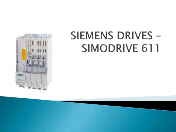
Operation/Programming 11/2002 Edition sinumerik ShopMill SINUMERIK 840D/840Di/810D
Introduction 1 Operation 2 SINUMERIK 840D/840Di/810D Programming with 3 ShopMill ShopMill Programming with 4 G Code Simulation 5 Operation/Programming File Management 6 Alarms and Messages 7 Examples 8 Appendix A Valid for Control SINUMERIK 840D SINUMERIK 840DE (export version) SINUMERIK 840D powerline SINUMERIK 840DE powerline SINUMERIK 840Di SINUMERIK 840DiE (export version) SINUMERIK 810D powerline SINUMERIK 810DE powerline Software version 6 6 6 6 2 2 6 6 11.02 Edition
SINUMERIK® Documentation Printing history Brief details of this edition and previous editions are listed below. The status of each edition is shown by the code in the "Remarks" column. Status codes in the "Remarks" column: A .... B .... C .... New documentation. Unrevised edition with new Order No. Revised edition with new status. Edition 10.97 11.98 03.99 08.00 12.01 11.02 Order No. 6FC5298-2AD10-0BP0 6FC5298-2AD10-0BP1 6FC5298-5AD10-0BP0 6FC5298-5AD10-0BP1 6FC5298-6AD10-0BP0 6FC5298-6AD10-0BP1 Comment A C C C C C This book is part of the documentation available on CD-ROM (DOCONCD) Edition Order No. 11.02 6FC5298-6CA00-0BG3 Comment C Trademarks SIMATIC®, SIMATIC HMI®, SIMATIC NET®, SIROTEC®, SINUMERIK® and SIMODRIVE® are trademarks of Siemens AG. Other product names in this documentation may be trademarks which, if used by third parties, could infringe the rights of their owners. Further information is available on the Internet under: http://www.ad.siemens.de/sinumerik Other functions not described in this documentation might be executable in the control. This does not, however, represent an obligation to supply such functions with a new control or when servicing. This publication was produced with WinWord V8.0 and Designer V6.0. The reproduction, transmission or use of this document or its contents is not permitted without express written authority. Offenders will be liable for damages. All rights, including rights created by patent grant or registration of a utility model or design, are reserved. We have checked that the contents of this document correspond to the hardware and software described. Nonetheless, differences might exist and we cannot therefore guarantee that they are completely identical. The information contained in this document is, however, reviewed regularly and any necessary changes will be included in the next edition. We welcome suggestions for improvement. © Siemens AG, 1997–2002. All rights reserved Subject to change without prior notice Siemens Aktiengesellschaft Order No. 6FC5298-6AD10-0BP1 Printed in Germany
0 Preface0 11.02 Preface The SINUMERIK documentation is organized in 3 parts: • General Documentation • User Documentation • Manufacturer/Service Documentation Structure of the documentation This documentation is intended for use by operators of vertical machining centers or universal milling machines controlled by the SINUMERIK 840D/840Di/810D system. Target group This Operator's/Programming Guide is valid for ShopMill SW 6.3 with • SINUMERIK 810D (SW 6.3 and later) • SINUMERIK 840D (SW 6.3 and later) • SINUMERIK 840Di (SW 2.2 and later) Validity Please address any queries to the following hotline: A&D Technical Support Tel.: +49 (0) 180 5050-222 Fax: +49 (0) 180 5050-223 Email: adsupport@siemens.com Hotline If you have any queries (suggestions, corrections) concerning the documentation, please send them to the following fax number or email address: Fax: +49 (0) 9131 98-2176 Fax form at the end of the documentation Email: motioncontrol.docu@erlf.siemens.de http://www.ad.siemens.de/sinumerik Internet address As of 09.2001, improved-performance variants SINUMERIK 840D powerline and SINUMERIK 840DE powerline are available. For a list of available powerline modules, please refer to the following Hardware Description: Reference: /PHD/, SINUMERIK 840D Configuration Manual SINUMERIK 840D powerline As of 12.2001, improved-performance variants SINUMERIK 810D powerline and SINUMERIK 810DE powerline are available from. For a list of available powerline modules, please refer to the following Hardware Description: Reference: /PHC/, SINUMERIK 810D Configuration Manual SINUMERIK 810D powerline This Operator's/Programming Guide describes the functionality of the ShopMill operator interface. Extensions or changes made by the machine tool manufacturer are documented by the machine tool manufacturer. Standard scope © Siemens AG, 2002. All rights reserved SINUMERIK 840D/840Di/810D, ShopMill Operation/Programming (BAS) - 11.02 Edition 0-5
0 11.020 Preface More detailed information about other publications relating to SINUMERIK 840D/840Di/810D and publications that apply to all SINUMERIK controls (e.g. Universal Interface, Measuring Cycles...) can be obtained from your local Siemens branch office. Other functions not described in this documentation might be executable in the control. This does not, however, represent as obligation to supply such functions with a new control or when servicing. Your SIEMENS 840D/840Di/810D with ShopMill has been designed and constructed according to state-of-the-art technology and approved safety regulations and standards. Principle SIEMENS offers special add-on equipment, products and system configurations for the focused expansion of SIEMENS controls in your field of application. Additional equipment Personnel Only suitably trained, authorized, reliable personnel should be allowed to handle the equipment. Persons who are not qualified should never be allowed to work on the control, even for a short time. The relevant responsibilities of personnel who set up, operate and maintain the equipment must be clearly defined and adherence to these responsibilities monitored. Procedure Before the control is started up, it should be ensured that the Operator's Guides have been read and understood by the people responsible. The operator also has a permanent obligation to continuously monitor the overall technical condition (externally recognizable defects and damage and changes in the operating behavior) of the control. Servicing Repairs must be carried out by personnel who are specially trained and qualified in the relevant technical subject according to the information supplied in the service and maintenance guide. All appropriate safety specifications must be observed. The following is deemed to be improper usage and exempts the manufacturer from any liability: • Any application deviating from the above points or usage extending beyond the given limits. • Cases where the control is not maintained in perfect technical condition, or is operated without due regard to safety or danger, and cases where any or all of the instructions in the Operator's Guide have not been observed. • If faults that might affect the safety of the equipment are not © Siemens AG, 2002. All rights reserved 0-6 SINUMERIK 840D/840Di/810D, ShopMill Operation/Programming (BAS) - 11.02 Edition
0 Preface0 11.02 rectified before the control is started up. Any modification, bypassing or disabling of items of equipment on the control that are required to ensure fault-free operation, unlimited use and active and passive safety. • Improper usage gives rise to unforeseen dangers to • life and limb of personnel, • the control, machine or other assets of the owner and the user. This documentation uses the following information blocks, identified by pictograms: Structure of the documentation Function Operating sequence Explanation of parameters Additional notes Software option The function described is a software option. This means that the function will only run on the control if you have purchased the relevant option. The following 5 warnings with varying degrees of severity are used in this documentation. Warnings Danger This symbol indicates that death, grievous injury or substantial property damage will occur if the appropriate precautions are not taken. Warning This symbol indicates that death, grievous injury or substantial property damage may occur if the appropriate precautions are not taken. Caution This symbol indicates that minor injuries or property damage may occur if the appropriate precautions are not taken. © Siemens AG, 2002. All rights reserved SINUMERIK 840D/840Di/810D, ShopMill Operation/Programming (BAS) - 11.02 Edition 0-7
0 11.020 Preface Caution This warning (without a warning triangle) indicates that property damage may occur if the appropriate precautions are not taken. Attention This warning indicates that an undesired event or state may occur if the appropriate precautions are not taken. If changes or additions exist for a particular topic, they are referenced here: Machine manufacturer Please observe the details provided by the machine manufacturer. Further references for particular topics are indicated here: References Reference: A complete list of available literature is included in the Appendix of this Operator's Guide. The meanings of several fundamental terms used in this documentation are defined below: Terms Program A program is a sequence of instructions for the CNC control, which produce a particular workpiece at the machine. Contour A contour outlines a workpiece. The term "contour" is also used to denote the section of a program that uses individual elements to define the outline of a workpiece. Cycle A cycle, for example, mill rectangular pocket, is a subroutine specified by ShopMill to execute a repetitive machining process. (a cycle is sometimes also called a "function".) © Siemens AG, 2002. All rights reserved 0-8 SINUMERIK 840D/840Di/810D, ShopMill Operation/Programming (BAS) - 11.02 Edition
0 Preface0 11.02 The parameter units are always specified in metric units in this documentation. The corresponding inch measures are given in the table below. "Unit of measurement" Metric mm mm/tooth mm/min mm/rev m/min Inch in in/tooth in/min in/rev ft/min © Siemens AG, 2002. All rights reserved SINUMERIK 840D/840Di/810D, ShopMill Operation/Programming (BAS) - 11.02 Edition 0-9
0 11.020 Preface Notes © Siemens AG, 2002. All rights reserved 0-10 SINUMERIK 840D/840Di/810D, ShopMill Operation/Programming (BAS) - 11.02 Edition
0 Contents0 11.02 Contents Introduction 1-17 1.1 The ShopMill product ................................................................................................1-18 1.2 1.2.1 1.2.2 1.2.3 1.2.4 1.2.5 Workstation...............................................................................................................1-19 Operator panels ........................................................................................................1-19 Operator panel keys..................................................................................................1-22 Machine control panel...............................................................................................1-24 Elements on the machine control panels..................................................................1-24 Mini handheld unit.....................................................................................................1-28 1.3 1.3.1 1.3.2 1.3.3 1.3.4 User interface............................................................................................................1-30 Overview ...................................................................................................................1-30 Operation via soft key and keys................................................................................1-32 Program views ..........................................................................................................1-36 Setting parameters....................................................................................................1-40 1.4 1.4.1 1.4.2 1.4.3 1.4.4 1.4.5 1.4.6 1.4.7 1.4.8 Fundamentals ...........................................................................................................1-42 Rectangular coordinate system.................................................................................1-42 Plane designations....................................................................................................1-42 Polar coordinates ......................................................................................................1-43 Absolute dimension...................................................................................................1-44 Incremental dimension..............................................................................................1-44 Pocket calculator function.........................................................................................1-45 Inch/metric dimension system switchover.................................................................1-46 Switchover between machine and workpiece coordinate systems...........................1-47 Operation 2-49 2.1 2.1.1 Power ON and reference point approach..................................................................2-51 User confirmation with Safety Integrated..................................................................2-54 2.2 2.2.1 2.2.2 2.2.3 2.2.4 2.2.5 2.2.6 2.2.7 2.2.8 Manual mode and settings for manual mode............................................................2-55 Traverse the machine axes.......................................................................................2-55 Load tool from list into spindle...................................................................................2-56 Enter a new tool in the list and load it to the spindle.................................................2-57 Enter a new tool in the list and load it in the magazine.............................................2-58 Start, stop and position the spindle manually............................................................2-58 Machine-specific functions........................................................................................2-60 Switch over machining plane/tool axis ......................................................................2-60 Switch over to mm or inches.....................................................................................2-61 2.3 Set a new position value ...........................................................................................2-62 2.4 2.4.1 2.4.2 2.4.3 Measure workpiece zero...........................................................................................2-64 Manual measurement ...............................................................................................2-64 Automatic measurement...........................................................................................2-69 Calibrate electronic measuring tool...........................................................................2-74 2.5 2.5.1 Measure tools............................................................................................................2-76 Measure tool manually..............................................................................................2-76 © Siemens AG, 2002. All rights reserved SINUMERIK 840D/840Di/810D, ShopMill Operation/Programming (BAS) - 11.02 Edition 0-11
0 11.020 Contents 2.5.2 2.5.3 Measuring tools with a probe.....................................................................................2-78 Calibrate measuring probe........................................................................................2-81 2.6 2.6.1 2.6.2 2.6.3 Machining in Manual mode........................................................................................2-82 Change settings.........................................................................................................2-82 Positioning.................................................................................................................2-83 Face milling ...............................................................................................................2-83 2.7 MDI mode..................................................................................................................2-85 2.8 2.8.1 2.8.2 2.8.3 2.8.4 2.8.5 2.8.6 2.8.7 2.8.8 2.8.9 Automatic mode ........................................................................................................2-86 Switchover between "T, F, S", "G functions" and "Auxiliary functions" displays........2-87 Select a program for execution .................................................................................2-88 Start/stop/abort program ...........................................................................................2-89 Interrupt program.......................................................................................................2-90 Start execution at specific program location..............................................................2-91 Program control.........................................................................................................2-94 Program testing.........................................................................................................2-95 Simultaneous recording before machining................................................................2-96 Simultaneous recording during machining................................................................2-97 2.9 2.9.1 2.9.2 2.9.3 Execute a trial program run.......................................................................................2-98 Single block...............................................................................................................2-98 Basic block display....................................................................................................2-99 Correct program ......................................................................................................2-100 2.10 2.10.1 2.10.2 2.10.3 2.10.4 2.10.5 2.10.6 2.10.7 2.10.8 2.10.9 2.10.10 2.10.11 2.10.12 2.10.13 2.10.14 2.10.15 Tools and tool offsets..............................................................................................2-101 Create a new tool ....................................................................................................2-105 Create several cutting edges per tool......................................................................2-106 Change the tool name.............................................................................................2-107 Create a replacement tool.......................................................................................2-107 Manual tools............................................................................................................2-107 Tool offsets..............................................................................................................2-108 Special tool functions...............................................................................................2-111 Create tool wear data..............................................................................................2-112 Tool monitoring........................................................................................................2-113 Magazine list............................................................................................................2-114 Delete a tool ............................................................................................................2-115 Change the tool type ...............................................................................................2-115 Load a tool...............................................................................................................2-116 Unload a tool ...........................................................................................................2-117 Sort tools .................................................................................................................2-118 2.11 2.11.1 2.11.2 2.11.3 Work offsets............................................................................................................2-119 Defining a work offset..............................................................................................2-121 Work offset list.........................................................................................................2-122 Select/deselect work offset in the Manual area.......................................................2-124 2.12 Switching to CNC ISO operation.............................................................................2-125 2.13 ShopMill Open (PCU 50).........................................................................................2-126 2.14 Remote diagnosis....................................................................................................2-126 © Siemens AG, 2002. All rights reserved 0-12 SINUMERIK 840D/840Di/810D, ShopMill Operation/Programming (BAS) - 11.02 Edition
0 Contents0 11.02 Programming with ShopMill 3-127 3.1 Fundamental programming principles.....................................................................3-129 3.2 Program structure ...................................................................................................3-132 3.3 3.3.1 3.3.2 3.3.3 3.3.4 Create a ShopMill program .....................................................................................3-133 Create new program; define a blank.......................................................................3-133 Program new blocks................................................................................................3-136 Change program blocks..........................................................................................3-138 Program editor ........................................................................................................3-139 3.4 Program the tool, offset value and spindle speed...................................................3-142 3.5 3.5.1 3.5.2 3.5.3 3.5.4 3.5.5 3.5.6 3.5.7 3.5.8 3.5.9 Contour milling ........................................................................................................3-143 Free contour programming .....................................................................................3-144 Description of soft keys for free contour programming function .............................3-147 Description of parameters for line/circle contour elements.....................................3-149 Programming examples for freely defined contours ...............................................3-150 Path milling of open and closed contours ...............................................................3-153 Rough drilling in contour pockets............................................................................3-156 Machine (rough cut) pocket with islands.................................................................3-159 Remove residual material .......................................................................................3-160 Finish pocket with islands .......................................................................................3-162 3.6 3.6.1 3.6.2 3.6.3 3.6.4 3.6.5 3.6.6 3.6.7 3.6.8 Straight line or circular path motions.......................................................................3-164 Line..........................................................................................................................3-165 Circle with known center point ................................................................................3-167 Circle with known radius .........................................................................................3-168 Helix ........................................................................................................................3-169 Polar coordinates ....................................................................................................3-170 Polar line .................................................................................................................3-171 Polar circle ..............................................................................................................3-172 Programming examples for polar coordinates........................................................3-173 3.7 3.7.1 3.7.2 3.7.3 3.7.4 3.7.5 3.7.6 3.7.7 3.7.8 3.7.9 3.7.10 3.7.11 3.7.12 3.7.13 3.7.14 3.7.15 Drilling .....................................................................................................................3-174 Centering.................................................................................................................3-175 Drilling and reaming ................................................................................................3-176 Deep-hole drilling ....................................................................................................3-177 Boring......................................................................................................................3-179 Tapping ...................................................................................................................3-180 Thread cutting.........................................................................................................3-181 Drill and thread milling.............................................................................................3-184 Position on freely programmable positions and position patterns...........................3-186 Freely programmable positions...............................................................................3-187 Line position pattern................................................................................................3-188 Matrix position pattern.............................................................................................3-189 Full circle position pattern .......................................................................................3-190 Pitch circle position pattern .....................................................................................3-192 Obstacle..................................................................................................................3-193 Repeat positions .....................................................................................................3-194 © Siemens AG, 2002. All rights reserved SINUMERIK 840D/840Di/810D, ShopMill Operation/Programming (BAS) - 11.02 Edition 0-13
0 11.020 Contents 3.7.16 Programming examples for drilling..........................................................................3-195 3.8 3.8.1 3.8.2 3.8.3 3.8.4 3.8.5 3.8.6 3.8.7 3.8.8 Milling ......................................................................................................................3-197 Face milling .............................................................................................................3-197 Rectangular pocket .................................................................................................3-200 Circular pocket ........................................................................................................3-204 Rectangular spigot...................................................................................................3-207 Circular spigot..........................................................................................................3-209 Mill longitudinal slot .................................................................................................3-212 Circumferential slot..................................................................................................3-214 Use of position patterns for milling..........................................................................3-216 3.9 3.9.1 3.9.2 3.9.3 Measurements.........................................................................................................3-219 Measure workpiece zero .........................................................................................3-219 Measure tool............................................................................................................3-221 Calibrate the measuring probe................................................................................3-222 3.10 3.10.1 3.10.2 3.10.3 3.10.4 3.10.5 3.10.6 3.10.7 3.10.8 Miscellaneous functions ..........................................................................................3-223 Call subroutine.........................................................................................................3-223 Repeat program blocks...........................................................................................3-224 Change program settings........................................................................................3-226 Call work offsets......................................................................................................3-227 Define coordinate transformation............................................................................3-228 Cylinder peripheral surface transformation .............................................................3-231 Swiveling .................................................................................................................3-234 Miscellaneous functions ..........................................................................................3-239 3.11 Insert G code in the ShopMill program....................................................................3-240 Programming with G Code 4-243 4.1 Create a G code program........................................................................................4-244 4.2 Execute G code program ........................................................................................4-247 4.3 G code editor...........................................................................................................4-249 4.4 Arithmetic parameters.............................................................................................4-252 4.5 ISO dialects.............................................................................................................4-253 Simulation 5-255 5.1 General....................................................................................................................5-256 5.2 Start/abort program .................................................................................................5-256 5.3 Representation as a plan view ................................................................................5-258 5.4 Representation as a 3-plane view...........................................................................5-259 5.5 Zoom a finished part viewport .................................................................................5-260 5.6 5.6.1 5.6.2 5.6.3 Three-dimensional representation of finished part..................................................5-261 Change position of finished part..............................................................................5-261 Cut open finished part .............................................................................................5-262 Update finished part display....................................................................................5-262 © Siemens AG, 2002. All rights reserved 0-14 SINUMERIK 840D/840Di/810D, ShopMill Operation/Programming (BAS) - 11.02 Edition
0 Contents0 11.02 File Management 6-263 6.1 Manage programs with ShopMill.............................................................................6-264 6.2 6.2.1 6.2.2 6.2.3 6.2.4 6.2.5 6.2.6 6.2.7 6.2.8 6.2.9 6.2.10 6.2.11 6.2.12 Manage programs with PCU 20..............................................................................6-265 Open program.........................................................................................................6-267 Execute a program..................................................................................................6-268 Multiple clamping ....................................................................................................6-268 Execute G code program from floppy disk drive or network drive ..........................6-271 Create new directory/program.................................................................................6-272 Select several programs .........................................................................................6-273 Copying/renaming directories/programs.................................................................6-274 Deleting directories/programs.................................................................................6-275 Execute program via RS-232 interface...................................................................6-276 Read program in/out via RS-232 interface..............................................................6-277 Display error log......................................................................................................6-279 Save/read in tool data/zero point data.....................................................................6-279 6.3 6.3.1 6.3.2 6.3.3 6.3.4 6.3.5 6.3.6 6.3.7 6.3.8 6.3.9 6.3.10 6.3.11 6.3.12 Manage programs with PCU 50..............................................................................6-282 Open program.........................................................................................................6-284 Execute a program..................................................................................................6-285 Multiple clamping ....................................................................................................6-286 Loading/unloading program ....................................................................................6-288 Execute G code program from hard disk, floppy disk drive or network drive..........6-289 Create new directory/program.................................................................................6-291 Select several programs .........................................................................................6-292 Copying/renaming/moving directories/programs ....................................................6-293 Deleting directories/programs.................................................................................6-295 Execute program via RS-232 interface...................................................................6-296 Display error log......................................................................................................6-298 Save/read in tool data/zero point data.....................................................................6-298 Alarms and Messages 7-301 7.1 7.1.1 7.1.2 7.1.3 Cycle alarms and messages...................................................................................7-302 Error treatment in cycles.........................................................................................7-302 Cycle alarm overview..............................................................................................7-302 Messages in cycles.................................................................................................7-307 7.2 7.2.1 7.2.2 7.2.3 Alarms for ShopMill.................................................................................................7-308 Alarm overview........................................................................................................7-308 Select the alarm/message overview .......................................................................7-309 Description of alarms ..............................................................................................7-310 7.3 User data.................................................................................................................7-318 7.4 Version display........................................................................................................7-320 Examples 8-321 8.1 Example 1: Machine with rectang./circ. pocket and circumf. slot ...........................8-322 8.2 Example 2: Shift and mirror a contour ....................................................................8-330 © Siemens AG, 2002. All rights reserved SINUMERIK 840D/840Di/810D, ShopMill Operation/Programming (BAS) - 11.02 Edition 0-15
0 11.020 Contents 8.3 Example 3: Chamfer on circular spigot ...................................................................8-333 8.4 Example 4: Cylinder surface transformation ...........................................................8-336 8.5 Example 5: Slot side compensation........................................................................8-340 8.6 Example 6: Swiveling ..............................................................................................8-344 Appendix A-351 A Abbreviations...........................................................................................................A-352 B References..............................................................................................................A-355 C Index........................................................................................................................A-369 © Siemens AG, 2002. All rights reserved 0-16 SINUMERIK 840D/840Di/810D, ShopMill Operation/Programming (BAS) - 11.02 Edition
1 Introduction1 11.02 Introduction 1.1 The ShopMill product ................................................................................................1-18 1.2 1.2.1 1.2.2 1.2.3 1.2.4 1.2.5 Workstation...............................................................................................................1-19 Operator panels ........................................................................................................1-19 Operator panel keys..................................................................................................1-22 Machine control panel...............................................................................................1-24 Elements on the machine control panels..................................................................1-24 Mini handheld unit.....................................................................................................1-28 1.3 1.3.1 1.3.2 1.3.3 1.3.4 User interface............................................................................................................1-30 Overview ...................................................................................................................1-30 Operation via soft key and keys................................................................................1-32 Program views ..........................................................................................................1-36 Setting parameters....................................................................................................1-40 1.4 1.4.1 1.4.2 1.4.3 1.4.4 1.4.5 1.4.6 1.4.7 1.4.8 Fundamentals ...........................................................................................................1-42 Rectangular coordinate system.................................................................................1-42 Plane designations....................................................................................................1-42 Polar coordinates ......................................................................................................1-43 Absolute dimension...................................................................................................1-44 Incremental dimension..............................................................................................1-44 Pocket calculator function.........................................................................................1-45 Inch/metric dimension system switchover.................................................................1-46 Switchover between machine and workpiece coordinate systems...........................1-47 © Siemens AG, 2002. All rights reserved SINUMERIK 840D/840Di/810D, ShopMill Operation/Programming (BAS) - 11.02 Edition 1-17
1 1 Introduction 1.1 11.02 The ShopMill product 1.1 The ShopMill product The ShopMill operating and programming software has been designed to perform 2½D milling operations on vertical and universal milling machinery with a maximum of 5 axes (including 2 rotary axes) and 1 spindle. The recommended hardware base for ShopMill is a SINUMERIK 840D/840Di/810D with PCU 20 or PCU 50. ShopMill has been designed such that machine users can learn quickly and easily how to operate and program the SINUMERIK 840D/840Di/810D CNC control system. The standard operator interface provides access to the full functional scope of the SINUMERIK 840D/840Di/810D. Workpieces are programmed graphically, i.e. the user does not need to have G code programming expertise. • Clear program overview in the machining plan • Dynamic input graphics (programming graphics) for contour elements and cycles • Simultaneous recording (option) • Contour pocket cycles with residual material sensing and residual material machining (option) • 3D graphics of finished part • Optimum adjustment of tool traversing paths taking account of workpiece contour and obstacles • Powerful contour computer for entry of freely defined contours • Automatic generation of approach and retract motions depending on the tool position and machining type • Network support and diskette drive connection (option) • Support for inclinable heads and tilting tables • Multiface machining, multiple clamping • Remote diagnostics (option) • Custom user screens - incl. cycle support Highlights Before actuating any of the control elements on this panel: Please read all the relevant explanations in this document carefully! © Siemens AG, 2002. All rights reserved 1-18 SINUMERIK 840D/840Di/810D, ShopMill Operation/Programming (BAS) - 11.02 Edition
1 Workstation 1 11.02 Introduction 1.2 1.2 Workstation 1.2.1 Operator panels Alternatively, you can also use one of the following operator panels for the PCUs: OP 010 OP 010C OP 010S with OP 032S full CNC keyboard OP 012 OP 015 with full 19" CNC keyboard OP 010 operator panel 4 1 . 5 6 3 2 2 OP 010 operator panel 1 10'' screen 2 Screen keys 3 Horizontal soft key bar 4 Verticalsoft key bar 5 Alphanumerical keypad Correction/cursor keypad with control keyboard and input key 6 USB interface © Siemens AG, 2002. All rights reserved SINUMERIK 840D/840Di/810D, ShopMill Operation/Programming (BAS) - 11.02 Edition 1-19
1 1 Introduction 1.2 11.02 Workstation OP 010C operator panel 4 . 1 5 6 3 2 2 OP 010C operator panel 1 10'' screen 2 Screen keys 3 Horizontal soft key bar 4 Verticalsoft key bar 5 Alphanumerical keypad Correction/cursor keypad with control keyboard and input key 6 USB interface OP 010S slimline operator panel 1 A 2 A 2 A 4 A 3 5 OP 010S operator panel 1 2 3 4 5 10'' screen Screen keys Horizontal soft key bar Vertical soft key bar USB interface © Siemens AG, 2002. All rights reserved 1-20 SINUMERIK 840D/840Di/810D, ShopMill Operation/Programming (BAS) - 11.02 Edition
1 Workstation 1 11.02 Introduction 1.2 OP 012 operator panel A 5 A 4 A 4 1 A 3 6 A 2 7 A 2 OP 012 operator panel 1 12'' screen 2 Screen keys 3 Horizontal soft key bar 4 Verticalsoft key bar 5 Alphanumerical keypad Correction/cursor keypad with control keyboard and input key 6 USB interface 7 Mouse OP 015 operator panel A 4 1 5 A 2 A 2 A 3 OP 015 operator panel 1 2 3 4 5 15'' screen Screen keys Horizontal soft key bar Vertical soft key bar USB interface © Siemens AG, 2002. All rights reserved SINUMERIK 840D/840Di/810D, ShopMill Operation/Programming (BAS) - 11.02 Edition 1-21
1 1 Introduction 1.2 11.02 Workstation 1.2.2 Operator panel keys Alarm Cancel Cancel the alarm that is characterized by this symbol. Channel Has no meaning for ShopMill. Help Change between machining plan and programming graphics as well as between parameter screen with programming graphics and parameter screen with help display. Next Window Has no meaning for ShopMill. Page Up or Page Down Page up or down in the directory or machining plan. Cursor Move between different fields or lines. Cursor right opens a directory or program. Cursor left changes to the next higher directory level. Select Select from several specified options. This key corresponds to the "Alternative" soft key. End Move cursor to the last input field in a parameter screen. Backspace • Delete value in the input field. • In insert mode, delete the character preceding the cursor. Tab Has no meaning for ShopMill. Shift Press the Shift key to output the characters at the top of the keys with dual assignment. © Siemens AG, 2002. All rights reserved 1-22 SINUMERIK 840D/840Di/810D, ShopMill Operation/Programming (BAS) - 11.02 Edition
1 Workstation 1 11.02 Introduction 1.2 Ctrl Used in the following key combinations in the machining plan and G code editor: • Ctrl + Pos1: jump to beginning. • Ctrl + End: jump to end. Alt Has no meaning for ShopMill. Del - now with OP 031 • Delete value in the parameter field. • In insert mode, deletes the character where the cursor is positioned. Insert Activate insert mode or pocket calculator. Input • Complete input of a value in the input field. • Open a directory or program. Alarm - OP 010 and OP 010C only Invoke "Messages/Alarms" operating area. This key corresponds to the "Messages/Alarms" soft key. Program - OP 010 and OP 010C only Invoke "Program" operating area. This key corresponds to the "Program" soft key. Offset - OP 010 and OP 010C only Invoke "Tools/Work Offsets" operating area. This key corresponds to the "Tools/Work Offset" soft key. Program Manager - OP 010 and OP 010C only Invoke "Program Manager" operating area. This key corresponds to the "Program Manager" soft key. © Siemens AG, 2002. All rights reserved SINUMERIK 840D/840Di/810D, ShopMill Operation/Programming (BAS) - 11.02 Edition 1-23
1 1 Introduction 1.2 11.02 Workstation 1.2.3 Machine control panel A SIEMENS machine control panel or a machine control panel supplied by the machine manufacturer can be connected to the turning machine. For example, the standard machine control panel (19'') or the slimline operator control panel OP 032S from SIEMENS. You trigger actions on the turning machine from the machine control panel, e.g. traversing axes or machining the workpiece. When the associated functions are active, the LEDs on the machine panel light up. 1.2.4 Elements on the machine control panels Emergency Stop button Press pushbutton in emergency situations, i.e. if there is a threat to life or limb of an operator, or if the machine or the workpiece risk being damaged. All drives are stopped with the greatest possible braking torque. For more information about responses when activating the emergency stop button, please refer to the machine manufacturer's specifications. Reset • Execution of the active program is aborted. The NC controller remains synchronized with the machine. It is in the initial setting and ready for the next program run. Delete alarm Reset • Jog Activate Machine Manual mode. Jog Teach In Has no meaning for ShopMill. Teach In MDI Activate MDI mode. MDA Auto Activate Machine Auto mode. Auto © Siemens AG, 2002. All rights reserved 1-24 SINUMERIK 840D/840Di/810D, ShopMill Operation/Programming (BAS) - 11.02 Edition
1 Workstation 1 11.02 Introduction 1.2 Single Block Execute program non-modally (single block). Single Block Repos Repositioning, re-approach contour. Repos Ref Point Approach reference point. Ref Point Inc Var (incremental feed variable) Incremental feed with variable step sizes. VAR Inc (Incremental Feed) Incremental feed with preset step size of 1, ..., 10000 increments. 1 10000 ... The increment value is evaluated as a function of a machine data. Please read the machine manufacturer's instructions. Cycle Start Start program execution. Cycle Start Cycle Stop Stop program execution. Cycle Stop Axis keys Select axis. X 5th Axis ... Direction keys Traverse axis in negative or positive direction. + Rapid Traverse axis in rapid traverse (fastest speed). Rapid WCS MCS Switch between tool coordinate system (Work) and machine coordinate system (Machine). WCS MCS © Siemens AG, 2002. All rights reserved SINUMERIK 840D/840Di/810D, ShopMill Operation/Programming (BAS) - 11.02 Edition 1-25
1 1 Introduction 1.2 11.02 Workstation Feedrate/rapid traverse override Increase or decrease programmed feed or rapid traverse. The programmed feed or rapid traverse corresponds to 100% and can be set between 0% and 120%, in rapid traverse to a maximum of 100%. The newly set feed is displayed in the feed status bar on the screen as an absolute value and as a percent value. % Feed Stop Stop processing the active program and stop the axis drives moving. Feed Stop Feed Start Continue program execution in the current block and accelerate feed to the value set in the program. Feed Start Spindle override Decrease or increase programmed spindle speed. The programmed spindle speed corresponds to 100% and can be set from 50 to 120%. The newly set spindle speed is displayed in the spindle status bar on the screen as an absolute value and as a percent value. % Spindle Dec. – OP032S machine control panel only Decrease programmed spindle speed. Spindle Dec. Spindle Inc. – OP032S machine control panel only Increase programmed spindle speed. Spindle Inc. 100% – OP032S machine control panel only Set programmed spindle speed again. 100% Spindle Stop Stop the spindle. Spindle Stop Spindle Start Start the spindle. Spindle Start Spindle Left – machine control panel OP032S only Start spindle (CCW rotation). Spindle Left Spindle Right – machine control panel OP032S only Start spindle (CW rotation). Spindle Right © Siemens AG, 2002. All rights reserved 1-26 SINUMERIK 840D/840Di/810D, ShopMill Operation/Programming (BAS) - 11.02 Edition
1 Workstation 1 11.02 Introduction 1.2 Keyswitch You can set different access rights via the keyswitch. The keyswitch has four settings with protection levels 4 to 7 assigned to them. Access to programs, data and functions can be disabled via machine data. You can set various levels of access protection. Please read the machine manufacturer's instructions. The keyswitch has three different-colored keys which you can remove in the specified positions: Position 0 No key Protection level 7 Lowest access authorization ↓ Increasing access authorization ↓ Highest authorization Position 1 Key 1black Protection level 6 Position 2 Key 1 green Protection level 5 Position 3 Key 1red Protection level 4 If you change the key position to modify the access authorization, you will not see the changes immediately on the screen. You first need to perform an action (e.g. open or close a directory). If the PLC is in STOP state (LEDs on the machine control panel are flashing), ShopMill does not evaluate the keyswitch settings at boot. The machine manufacturer can set protection levels 0 to 3 via a password. If this password is set, ShopMill does not assess the keyswitch setting. Please read the machine manufacturer's instructions. © Siemens AG, 2002. All rights reserved SINUMERIK 840D/840Di/810D, ShopMill Operation/Programming (BAS) - 11.02 Edition 1-27
1 1 Introduction 1.2 11.02 Workstation 1.2.5 Mini handheld unit 20 60 108 A G F E H 216 D B I C 88 83,5 A EMERGENCY STOP button, two-channel B Enabling key, two-channel C Axis selector switch for 5 axes and neutral position D Function keys F1, F2, F3 E Traversing keys, directions +, – F Rapid traverse key for high-speed travel with traversing keys or handwheel G Handwheel H Magnets for attachment to metal parts I 1.5 m ... 3.5 m connecting lead Control elements EMERGENCY STOP button Use the EMERGENCY STOP button in urgent situations, i.e. 1. when human life is at risk or 2. if there is a risk of damage to the machine tool or workpiece. Enabling key The enabling key has 2 settings. It must be pressed to initiate traversing movements. Axis selector switch You can select up to 5 axes with the axis selector switch. © Siemens AG, 2002. All rights reserved 1-28 SINUMERIK 840D/840Di/810D, ShopMill Operation/Programming (BAS) - 11.02 Edition
1 Workstation 1 11.02 Introduction 1.2 Function keys You can activate machine-specific functions with the function keys. Traversing keys The + and – traversing keys can be pressed to move the axis selected with the axis selector switch. Handwheel The handwheel can be used to move the axis selected with the axis selector switch. The handwheel supplies 2 track signals with 100 l/V. Rapid traverse key The rapid traverse key increases the traversing speed of the axis selected with the axis selector switch. The rapid traverse key acts both on travel commands from the +/– keys and on the handwheel signals. © Siemens AG, 2002. All rights reserved SINUMERIK 840D/840Di/810D, ShopMill Operation/Programming (BAS) - 11.02 Edition 1-29
1 1 Introduction 1.3 11.02 User interface 1.3 User interface 1.3.1 Overview Screen layout 14 1 2 4 5 6 3 8 7 13 9 10 11 12 15 15 14 User interface 1 Active operating mode/operating area and sub-operating mode 2 Alarm and message line 3 Program name 4 Program path 5 Channel status and program control 6 Channel status messages 7 Position display for axes 8 Display for • active tool T • current feed F • spindle S 9 Display the active work offsets and rotation 10 Working window 11 Dialog line for additional explanations 12 Horizontal soft key bar 13 Vertical soft key bar 14 Soft keys 15 Screen keys © Siemens AG, 2002. All rights reserved 1-30 SINUMERIK 840D/840Di/810D, ShopMill Operation/Programming (BAS) - 11.02 Edition
1 User interface 1 11.02 Introduction 1.3 REF: REPOS: INC1 ... INC10000: Fixed increment INC_VAR: Approach reference point Repositioning Submode Variable increment size Channel status RESET active interrupted SKP: Skip a G code block DRY: Dry run feed !ROV:Feedrate override only (not feedrate and rapid traverse override) SBL1:Single block (stop after each block that triggers a function on the machine) SBL2:Not possible to select in ShopMill (stop each every block) SBL3:Single block fine (stop after each block, even within the same cycle) M01: Programmed stop DRF: DRF offset PRT: Program test Program control Channel status messages Hold: Operator action is necessary. Wait: No operator action is necessary. Feed status Feed not enabled Spindle status Spindle not enabled Spindle motionless Spindle rotating CW Spindle rotating CCW The symbols are color-coded as follows: Red: Machine is not running Green: Machine is running Yellow: Waiting for operator action Gray: Other Screen keys Machine Call active operating mode (Machine Manual, MDI or Machine Auto). Return jump Has no meaning for ShopMill. © Siemens AG, 2002. All rights reserved SINUMERIK 840D/840Di/810D, ShopMill Operation/Programming (BAS) - 11.02 Edition 1-31
1 1 Introduction 1.3 11.02 User interface Expansion Change horizontal soft key bar. Menu Select Call main menu: Symbols defined by the machine manufacturer can be displayed instead of the program path (4). The program path is then displayed together with the program name (3). Please read the machine manufacturer's instructions. 1.3.2 Operation via soft key and keys The ShopMill user interface consists of different screens featuring eight horizontal and eight vertical soft keys. Operate the soft keys via the keys positioned next to the soft keys. Upon activation of a soft key, a new screen opens. ShopMill has 3 operating modes (Machine Manual, MDI and Machine Auto) and 4 operating areas (Program Manager, Program Messages/Alarms and Tools/Work Offsets). If you want to switch from one operating mode/operating area to another operating area, press the "Menu Select" key. The main menu is opened and you can select the required operating area by pressing the associated soft key. Alternatively, you can access the operating areas via the keys on the operator panel. You can select an operating mode at any time directly via the keys on the machine control panel. If you press the "Machine" soft key in the main menu, the screen belonging to the currently active operating mode opens. Auto MDA Jog © Siemens AG, 2002. All rights reserved 1-32 SINUMERIK 840D/840Di/810D, ShopMill Operation/Programming (BAS) - 11.02 Edition
1 User interface 1 11.02 Introduction 1.3 If you select another operating mode or another operating area, both the horizontal and the vertical soft key bar change. Main menu Machine Manual mode © Siemens AG, 2002. All rights reserved SINUMERIK 840D/840Di/810D, ShopMill Operation/Programming (BAS) - 11.02 Edition 1-33
1 1 Introduction 1.3 11.02 User interface If you activate a horizontal soft key within an operating mode or operating area, only the vertical soft key bar changes. Machine Manual mode Function within Machine Manual mode © Siemens AG, 2002. All rights reserved 1-34 SINUMERIK 840D/840Di/810D, ShopMill Operation/Programming (BAS) - 11.02 Edition
1 User interface 1 11.02 Introduction 1.3 If the symbol the dialog line, you can change the horizontal soft key bar within an operating area. To do this, press the "Expansion" soft key. If you press the "Expansion" soft key again, the original horizontal soft key bar is displayed again. is displayed on the operator interface on the right of To return to a next-level screen within an operating mode/operating area, press the "Back" soft key. Press the "Cancel" soft key to exit a screen without accepting the specified values and return to the next-level screen. If you have entered all the necessary parameters correctly in the parameter screen, press the "Accept" soft key to close the screen and validate the data. Pressing the "OK" soft key will trigger an immediate action, e.g. rename or delete a program. When some soft key functions are activated, the soft key background color will change to black to indicate the function in ON. To deactivate the function again, press the soft key again. The soft key will be gray again. ON Program test OFF © Siemens AG, 2002. All rights reserved SINUMERIK 840D/840Di/810D, ShopMill Operation/Programming (BAS) - 11.02 Edition 1-35
1 1 Introduction 1.3 11.02 User interface 1.3.3 Program views You can display a ShopMill program in various views. All the programs are administered in the Program Manager. You also use the Program Manager to select a program for workpiece machining. Program manager Program Manager Select the Program Manager by activating the "Program" soft key or the "Program Manager" key. -or- You can navigate within a directory by pressing the "Cursor up" and "Cursor down" keys. Use "Cursor right" to open a directory. Use the "Cursor left" key to return to the next higher directory level. Use the "Cursor right" or "Input" key to open the machining plan for a program. -or- © Siemens AG, 2002. All rights reserved 1-36 SINUMERIK 840D/840Di/810D, ShopMill Operation/Programming (BAS) - 11.02 Edition
1 User interface 1 11.02 Introduction 1.3 The machining plan provides an overview of the individual machining steps in a program. Machining plan Machining plan In the machining plan, you can use the "Cursor up" and "Cursor down" keys to navigate among the program blocks. Use the "Help" key to switch between the machining plan and programming graphics. The programming graphics display a dynamic broken-line top view of the workpiece. The program block selected in the machining plan is highlighted in color in the programming graphics. Programming graphic Programming graphic © Siemens AG, 2002. All rights reserved SINUMERIK 840D/840Di/810D, ShopMill Operation/Programming (BAS) - 11.02 Edition 1-37
1 1 Introduction 1.3 11.02 User interface Use the "Cursor right" key to open a program block in the machining plan. The associated parameter screen with programming graphics is opened. The programming graphics in the parameter screen show the contour of the active machining step as broken-line graphics as well as the parameters. Parameter screen with programming graphics Parameter screen with programming graphics You can use the cursor keys to navigate among the input fields in the parameter screen. Press the "Help" key to change between programming graphics and the help display in the parameter screen. © Siemens AG, 2002. All rights reserved 1-38 SINUMERIK 840D/840Di/810D, ShopMill Operation/Programming (BAS) - 11.02 Edition
1 User interface 1 11.02 Introduction 1.3 The help display in the parameter screen provides information about the individual parameters in the machining step. Parameter screen with help display Parameter screen with help display The color symbols in the help displays indicate the following: Yellow circle = reference point Red arrow = tool travelling in rapid traverse Green arrow = tool travelling at machining feedrate © Siemens AG, 2002. All rights reserved SINUMERIK 840D/840Di/810D, ShopMill Operation/Programming (BAS) - 11.02 Edition 1-39
1 1 Introduction 1.3 11.02 User interface 1.3.4 Setting parameters When setting up the machine and programming, you need to specify values for specific parameters in the white input fields. Parameters that have a gray input field are automatically calculated by ShopMill. White field input Gray field input Parameter Unit Parameter screen With some parameters the input field will offer you several options to select from. In these fields you cannot enter any data. Select parameters ! Keep pressing the "Alternative" soft key or the "Select" key until the desired setting is displayed. -or- The "Alternative" soft key is only visible if the cursor is positioned on an input field with more than one option. Similarly, the "Select" key is only effective if it is possible to make a selection. For the remaining parameters you need to enter a numerical value in the input field by using the keys on the operator panel. Setting parameters ! Enter the required value. ! Press the "Input" key to terminate your input. If you do not want to enter a value, i.e. not even value "0", press the "Backspace" or "Del" key. -or- © Siemens AG, 2002. All rights reserved 1-40 SINUMERIK 840D/840Di/810D, ShopMill Operation/Programming (BAS) - 11.02 Edition
1 User interface 1 11.02 Introduction 1.3 With some of these parameters, you can choose from different units. Select a unit ! Keep pressing the "Alternative" soft key or the "Select" key until the desired unit is displayed. -or- The "Alternative" soft key is only visible if you can select from different units for this parameter. Similarly, the "Select" key is only effective if it is possible to make a selection. If one of the input fields contains an incorrect value, you can delete the entire value. Delete parameter ! Press the "Backspace" or "Del" key. -or- If you do not want to overwrite the entire value in an input field, but only edit individual characters, change to insert mode. The pocket calculator is also active in this mode; you can use it to calculate parameter values during programming. Edit/calculate parameter ! Press the "Insert" key. Insert mode and the pocket calculator are activated. You can navigate within an input field by pressing the "Cursor left" and "Cursor right" keys. You can delete individual characters by pressing the "Backspace" or "Del" key. For more information about the pocket calculator, please refer to the section entitled "Pocket Calculator". If you have entered all the necessary parameters correctly in the parameter screen, you can exit the screen and save your settings. Accept parameters ! Press the "Accept" soft key or the "Cursor left" key. If there are more than one input fields in a line and you want to accept the parameter with the "Cursor left" key, you must place the cursor in the input field on the far left. -or- You cannot accept parameters if these are incomplete or largely incorrect. The dialog line will then inform you which parameters are missing or faulty. © Siemens AG, 2002. All rights reserved SINUMERIK 840D/840Di/810D, ShopMill Operation/Programming (BAS) - 11.02 Edition 1-41
1 1 Introduction 1.4 11.02 Fundamentals 1.4 Fundamentals 1.4.1 Rectangular coordinate system The principle of machining workpieces on a mill is based on a rectangular coordinate system consisting of three coordinate axes – X, Y and Z – which are parallel to the machine axes. The orientation of the coordinate system in relation to the machine is dependent on the machine type. The axis directions are governed by the so-called "Right-hand rule" (according to DIN 66217). Imagine you are standing in front of the machine with the middle finger on your right hand pointing in the infeed direction of the main spindle. The following then applies: • Your thumb is then pointing in direction +X, • your index finger in direction +Y and • your middle finger in direction +Z. Y Z +Z +Y +X X Machine coordinate system and "Right-hand rule" 1.4.2 Plane designations Each plane is defined by two coordinate axes. The third coordinate axis (tool axis) in each case is perpendicular to this plane and determines the infeed direction of the tool (e.g. for 2½ D milling operations). When you program a workpiece, you must specify the plane in which you are working so that the control can calculate the tool offset values correctly. The plane is also significant for certain types of circle programming and for polar coordinates. Z Y Y/Z Z/X X/Y X © Siemens AG, 2002. All rights reserved 1-42 SINUMERIK 840D/840Di/810D, ShopMill Operation/Programming (BAS) - 11.02 Edition
1 Fundamentals 1 11.02 Introduction 1.4 Working planes are defined as follows: Plane X/Y Z/X Y/Z Tool axis Z Y X 1.4.3 Polar coordinates The rectangular coordinate system is suitable in cases where dimensions in the production drawing are orthogonal. For workpieces dimensioned with arcs or angles, it is better to define positions using polar coordinates. This is possible if you are programming a straight line or a circle (see Section "Program simple path motions"). Polar coordinates have their zero point in the "pole". Example: Using this system, points P1 and P2 could be defined as follows – in relation to the pole –: P1:Radius =100 plus angle =30° P2:Radius =60 plus angle =75° Y P2 P1 60 100 75° 30° Pole 30 X 15 © Siemens AG, 2002. All rights reserved SINUMERIK 840D/840Di/810D, ShopMill Operation/Programming (BAS) - 11.02 Edition 1-43
1 1 Introduction 1.4 11.02 Fundamentals 1.4.4 Absolute dimension With an absolute dimension, all position data always refer to the currently valid zero point. With respect to tool motion, this means: The absolute dimension describes the position to which the tool must move. Example: The positions for points P1 to P3 as absolute dimensions are as follows in relation to the zero point: P1: X20 Y35 P2: X50 Y60 P3: X70 Y20 Y P2 P1 60 P3 35 20 X 20 50 70 1.4.5 Incremental dimension In the case of production drawings in which dimensions refer to some other point on the workpiece rather than the zero point, it is possible to enter an incremental dimension. With an incremental dimension input, a position specification refers in each case to a point programmed beforehand. Example: The positions for points P1 to P3 as incremental dimensions are as follows: P1: X20 Y35 ;(in relation to the Y P2 20 P1 zero point) 15 P3 P2: X30 Y20 ;(in relation to P1) 20 X P3: X20 Y-35 ;(in relation to P2) 20 30 20 © Siemens AG, 2002. All rights reserved 1-44 SINUMERIK 840D/840Di/810D, ShopMill Operation/Programming (BAS) - 11.02 Edition
1 Fundamentals 1 11.02 Introduction 1.4 1.4.6 Pocket calculator function Function Precondition The cursor is positioned on a parameter field. Press the "Insert" key or Equal key to activate pocket calculator mode. To perform an arithmetic function on two values, press this key and then enter the symbol for the relevant function (+, –, *, / ) followed by a value. Then press the Input key and the second value to perform the calculation. = Example application: A tool wear value in length L of + 0.1 must be included in a tool calculation. • Place the cursor in the appropriate parameter setting field, • Press the Equals key to open the parameter field and • Add the new wear value to the existing value, e.g. 0.5 + 0.1 • Terminate calculation by pressing the "Input" key. Result: 0.6 © Siemens AG, 2002. All rights reserved SINUMERIK 840D/840Di/810D, ShopMill Operation/Programming (BAS) - 11.02 Edition 1-45
1 1 Introduction 1.4 11.02 Fundamentals 1.4.7 Inch/metric dimension system switchover Function This function enables you to switch between the metric and inch dimension systems depending on the dimension units used in your production drawing. Every dimension system switchover applies to the entire machine, i.e. all relevant measurement data are automatically converted to the new dimension system, e.g. • Positions • Tool offsets • Work offsets Operating sequence In "Machine Manual" operating mode change to the expanded horizontal soft key bar. Jog Press soft keys "ShopM. Settings" and "Inch" • Switch from metric to inches: Soft key is active Inch • Switch from inches to metric: Soft key is not active Inch When you press the "Inch" soft key, a prompt box appears asking you to confirm the switchover operation. The dimension system is adjusted correspondingly when you confirm with the "OK" soft key. © Siemens AG, 2002. All rights reserved 1-46 SINUMERIK 840D/840Di/810D, ShopMill Operation/Programming (BAS) - 11.02 Edition
1 Fundamentals 1 11.02 Introduction 1.4 1.4.8 Switchover between machine and workpiece coordinate systems Function The machine coordinate system (MCS) is the original system of your machine. In contrast to the workpiece coordinate system (WCS), it does not allow for tool offsets, work offset, scalings, etc. Operating sequence You can switch between the machine and workpiece coordinate systems by following the sequence below: Press the "WCS MCS" key on the machine control panel. WCS MCS or Select soft key "Actual value MCS" in "Machine Manual" or "Machine Auto" operating mode. Auto Jog • Switch from WCS (work) to MCS (machine): Soft key is active. Actual value MCS • Switch from MCS (work) to WCS (machine): Soft key is not active. Actual value MCS " © Siemens AG, 2002. All rights reserved SINUMERIK 840D/840Di/810D, ShopMill Operation/Programming (BAS) - 11.02 Edition 1-47
1 1 Introduction 1.4 11.02 Fundamentals Notes © Siemens AG, 2002. All rights reserved 1-48 SINUMERIK 840D/840Di/810D, ShopMill Operation/Programming (BAS) - 11.02 Edition
2 Operation2 11.02 Operation 2.1 2.1.1 Power ON and reference point approach..................................................................2-51 User confirmation with Safety Integrated..................................................................2-54 2.2 2.2.1 2.2.2 2.2.3 2.2.4 2.2.5 2.2.6 2.2.7 2.2.8 Manual mode and settings for manual mode............................................................2-55 Traverse the machine axes.......................................................................................2-55 Load tool from list into spindle...................................................................................2-56 Enter a new tool in the list and load it to the spindle.................................................2-57 Enter a new tool in the list and load it in the magazine.............................................2-58 Start, stop and position the spindle manually............................................................2-58 Machine-specific functions........................................................................................2-60 Switch over machining plane/tool axis ......................................................................2-60 Switch over to mm or inches.....................................................................................2-61 2.3 Set a new position value ...........................................................................................2-62 2.4 2.4.1 2.4.2 2.4.3 Measure workpiece zero...........................................................................................2-64 Manual measurement ...............................................................................................2-64 Automatic measurement...........................................................................................2-69 Calibrate electronic measuring tool...........................................................................2-74 2.5 2.5.1 2.5.2 2.5.3 Measure tools............................................................................................................2-76 Measure tool manually..............................................................................................2-76 Measuring tools with a probe ....................................................................................2-78 Calibrate measuring probe........................................................................................2-81 2.6 2.6.1 2.6.2 2.6.3 Machining in Manual mode .......................................................................................2-82 Change settings ........................................................................................................2-82 Positioning.................................................................................................................2-83 Face milling...............................................................................................................2-83 2.7 MDI mode..................................................................................................................2-85 2.8 2.8.1 2.8.2 2.8.3 2.8.4 2.8.5 2.8.6 2.8.7 2.8.8 2.8.9 Automatic mode........................................................................................................2-86 Switchover between "T, F, S", "G functions" and "Auxiliary functions" displays........2-87 Select a program for execution.................................................................................2-88 Start/stop/abort program...........................................................................................2-89 Interrupt program ......................................................................................................2-90 Start execution at specific program location .............................................................2-91 Program control.........................................................................................................2-94 Program testing.........................................................................................................2-95 Simultaneous recording before machining................................................................2-96 Simultaneous recording during machining................................................................2-97 2.9 2.9.1 2.9.2 2.9.3 Execute a trial program run.......................................................................................2-98 Single block...............................................................................................................2-98 Basic block display....................................................................................................2-99 Correct program......................................................................................................2-100 2.10 2.10.1 Tools and tool offsets..............................................................................................2-101 Create a new tool....................................................................................................2-105 © Siemens AG, 2002. All rights reserved SINUMERIK 840D/840Di/810D, ShopMill Operation/Programming (BAS) - 11.02 Edition 2-49
2 11.022 Operation 2.10.2 2.10.3 2.10.4 2.10.5 2.10.6 2.10.7 2.10.8 2.10.9 2.10.10 2.10.11 2.10.12 2.10.13 2.10.14 2.10.15 Create several cutting edges per tool......................................................................2-106 Change the tool name.............................................................................................2-107 Create a replacement tool.......................................................................................2-107 Manual tools............................................................................................................2-107 Tool offsets..............................................................................................................2-108 Special tool functions...............................................................................................2-111 Create tool wear data..............................................................................................2-112 Tool monitoring........................................................................................................2-113 Magazine list............................................................................................................2-114 Delete a tool ............................................................................................................2-115 Change the tool type ...............................................................................................2-115 Load a tool...............................................................................................................2-116 Unload a tool ...........................................................................................................2-117 Sort tools .................................................................................................................2-118 2.11 2.11.1 2.11.2 2.11.3 Work offsets............................................................................................................2-119 Defining a work offset..............................................................................................2-121 Work offset list.........................................................................................................2-122 Select/deselect work offset in the Manual area.......................................................2-124 2.12 Switching to CNC ISO operation.............................................................................2-125 2.13 ShopMill Open (PCU 50).........................................................................................2-126 2.14 Remote diagnosis....................................................................................................2-126 © Siemens AG, 2002. All rights reserved 2-50 SINUMERIK 840D/840Di/810D, ShopMill Operation/Programming (BAS) - 11.02 Edition