Download
1 / 44
600 likes | 1.26k Views
Special Electrical Practice for Oil, Gas and Chemical Tankers. Seung-hwan , Lee. Index. Introduction. Tanker Classification. 01. 02. Some Factors. 03. Type of Explosion Protection. 04. Certification and Identification. References. Electrical Testing in Hazardous Area.

E N D
Special Electrical Practice for Oil, Gas and Chemical Tankers Seung-hwan, Lee
Index Introduction Tanker Classification 01 02 Some Factors 03 Type of Explosion Protection 04 Certification and Identification References Electrical Testing in Hazardous Area Maintenance of Ex-protected Apparatus 05 06 07 08
01 The object of all such guidance is to prevent the hazardous of fire and explosion occurring on boards oil, gas and liquid chemicals tank ships. Special electrical equipment is permitted in the hazardous area and this document will provide a guide to the range and maintenance of such explosion (Ex) protected equipment. Introduction Space in tankers where explosive gas-air mixtures may be expected to be present are called dangerous and hazardous
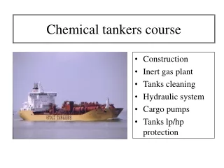
02 Type A Tankers Type B Tankers Type A : Oil tankers intended for carriage in bulk of non-boiling cargoes having a flash point (closed test) of 60℃ or less. e.g. crude oil carriers, gasoline carriers, etc. Type B : Oil tankers intended for carriage in bulk of non-boiling oil cargoes having a flash point (closed test) in excess of 60℃. e.g. tankers for carrying bituminous or asphalt products, or for carrying diesel or fuel oils. Tanker Classification Flash point : The lowest temperature at which the vapor of a combustible liquid can be made to ignite momentarily in air. Note : Don't confuse Flashpoint with Ignition Temperature (e.g. Kerosene, Flash point = 38 °C, Ignition Temp = 210 °C)
02 Type C Tankers (Gas Carriers) Type C : Gas carriers intended for the carriage in bulk of liquefied petroleum gas (LPG) or liquefied natural gas (LNG). • Dangerous Spaces : • A space in the cargo area which is not equipped with • approved arrangements. • An enclosed space outside the cargo area through • which any piping terminates. Tanker Classification
02 Tanker Classification • A cargo containment system with cargo piping : • (a) cargo containment system requiring a secondary • barrier; • (b) cargo containment system not requiring a • secondary barrier. • A space separated from a hold space described in (a) • above by a single gastight steel boundary. • A cargo pump room and cargo compressor room.
02 Tanker Classification • A zone on open deck, or semi-enclosed space on • open deck, within 3m of any cargo tank outlet, gas • or vapour outlet, cargo piped flange, cargo valve or • of entrances and ventilation openings to a cargo • pumproom and cargo compressor rooms. • The open deck over the cargo area and 3m forward • and aft of the cargo area on open deck up to a • height of 2.4m above the weather deck.
02 Tanker Classification • An enclosed or semi-enclosed space in which pipes • containing products are located. • A compartment for cargo hoses. • An enclosed or semi-enclosed space having a direct • opening into any dangerous space or area. There are two important additional recommendations for gas carriers.
02 Tanker Classification • Cargo Pump Motor • Submerged cargo pump motors and their cables are • permitted in cargo tanks subject to the atmosphere • of the tank being controlled to prevent presence of a • gas-air mixture when the motors are energised. • Gas Compressor Motors • These motors are allowed, under certain • circumstances, to be sited in the same space as the • compressors.
02 Type D Tankers (Chemical Carriers) Type D : Tanker for the carriage in bulk of other flammable liquid cargoes. This includes those cargoes which are potentially more dangerous than those conveyed by other type tankers, and those product which exhibit chemical instability. Tanker Classification
03 Hazardous Zone Shore practice for hazardous areas is to divide the areas into three zones(0, 1, 2). Zone 0 : In which an explosive gas-air mixture is continuously present, or present for long periods. e.g. Interior spaces of oil cargo tanks, pipes, pumps, etc Some Factors
03 Zone 2 : In which an explosive gas-air mixture is not likely to occur in normal operation and, if it occurs, will exist for only a short time. e.g. Open spaces on the deck of a tanker. Zone 1 : In which an explosive gas-air mixture is likely to occur in normal operation. e.g. Enclosed or semi-enclosed spaces on the deck of a tanker, the boiler firing area on a gas carrier using methane boil-off as a fuel and battery rooms. Some Factors
03 Some Factors
03 Electrical Ignition of Gas Some Factors SOURCE OF IGNITION (Something to start the explosion)
03 • Various electrical sources for ignition of gas • (Lower Flammable Limit Gases) : • Arcing between switch contacts. • Arcing between a live conductor and earth. • An internal arcing fault within an electrical enclosure. • Overheating causing hot spots. • An electrostatic spark discharge between charged • bodies or between a charged body and earth. • Chemical action. • Lightning strikes. Some Factors
03 Flammable ratio of gas A ratio of 100% gas/air concentration will not burn and, as can be expected, 0% will also not burn. Some Factors Higher flammable limit is typically listed as 81% but Acetylene can undergo an explosive decomposition reaction, even at concentrations of 100%.
03 Auto ignition temperature and Minimum ignition energy Some Factors The minimum temperature at which a substance will continue to burn without additional application of external heat.
03 Apparatus Gas Groups Gases associated with the mining industry are fire-classed as GROUP I, all other industrial gases are classed as GROUP II. Equipment certified for use in group IIC may also be used for IIA and IIB. Equipment certified for IIB may be used for IIA. Equipment certified for IIA may be used with no other group. Some Factors
03 Some Factors More easily ignited
03 Temperature Class This defines the maximum surface temperature of the components in the electrical equipment under normal and fault conditions. Some Factors
03 Some Factors Note : Don't confuse T class with maximum operating temperature
04 There are a number of different constructional techniques employed in preventing electrical equipment causing explosions in hazardous areas. Type of Explosion Protection Ex identification marks.
04 Explosion protected equipment be identified by the symbol “Ex”. Followed letters are indicating the type of protection. Type of Explosion Protection
04 Flameproof Enclosure (Exd) Exd protection uses a flameproof enclosure to contain the electrical apparatus. Type of Explosion Protection • The enclosure must be strong enough to withstand • an internal explosion. • The enclosure must prevent the flame and hot gases • from being transmitted to the external flammable • atmosphere. • The external surface temperature of the enclosure • must remain below the ignition temperature of the • surrounding gas.
04 The transmission of flame and hot gases from a flameproof enclosure is prevented. Type of Explosion Protection Exdflamepaths
04 The cable entry into an Exd enclosure must also be maintained flameproof. Type of Explosion Protection Exd cable gland
04 Intrinsic Safety (Exi) Exi means limiting the circuit conditions to less than 30V and 50mA. Electrical safety barrier : The purpose of such a barrier is to limit voltages and currents in the hazardous area. A separate barrier is required for each Exi circuit. Type of Explosion Protection Shunt diode safety barrier
04 • A safety (or zener) barrier comprises : • A fuse to limit the maximum current through the • shunt (zener) diodes. • A set of resistors to limit the maximum current. • A set of shunt connected zener diodes to limit • the maximum voltage. Type of Explosion Protection
04 Barrier under fault condition Type of Explosion Protection
04 • A galvanic isolation barrier comprises : • Breaks any direct connection between safe- and • hazardous-area circuits. • The power transfer is usually via some form of • transformer and the return signal via an optocoupler, • transformer or relay. • The final power limitation is achieved by using a • diode resistor network. Type of Explosion Protection Galvanic Isolation
04 Galvanic Isolator under fault condition Type of Explosion Protection
04 Comparisons Type of Explosion Protection
04 Type of Explosion Protection
04 Cables for intrinsically safe circuit aboard ships should be separated from power cables and the crossing over of such cables should be at 90°. The metallic cable screens of intrinsically safe circuit should be earthed. Power and intrinsically safe cable runs should be separately identified. Type of Explosion Protection
04 Increased Safety (Exe) Exe equipment is based primarily on the elimination of open sparking. e.g. relay and switch contacts or on the commutators or slip-rings of motors and generators, and on the close control of surface temperatures. Type of Explosion Protection Creepage and clearance distances
04 Non-Sparking (Exn) Exe enclosure is made to withstand impact and to prevent ingress of solids and liquids. e.g. Cage-roter induction motors, luminaires and connection boxes. Similar to Exe, Exn requirements are less stringent than for Exe and designs are very close to that of normal electrical apparatus. The main consideration is extra care to ensure locking of terminal connections. Type of Explosion Protection
04 Pressurised Enclosure (Exp) Special Protection (Exs) Clean, dry air or an inert gas is supplied to the equipment slightly above atmospheric. e.g. Sometimes used for motors, instrumentation enclosures and lighting. Exs includes precautions taken to prevent explosions which are not specifically covered by the previous designations. Type of Explosion Protection Exp (pressurised) enclosure arrangements
04 Type of Explosion Protection
05 When a manufacturer produces an item of explosion protected equipment, it must be tested and inspected to ensure that it complies with the required standards relating to that type of protection. Certification and Identification
06 All electrical apparatus and associated circuits are required to be tested periodically. Insulation resistance, earth loop resistance and earth continuity resistance tests are required. No apparatus should be opened in a danger area until it has been made dead and effective measures. Restore the power supply before the apparatus is reassembled. Insulation resistance testing should be carried out using a 500V d.c. tester of certified Exi design. Electrical Testing in Hazardous Area
06 The testing and maintenance of Exd or Exi equipment should be entrusted only to competent persons. The body material of instruments and tools required for maintenance purposes should be designed so that they will not make a hot spark when dropped. The energy output of all Exi instruments should be so small. An insulation tester has a drooping characteristic to prevent high current. Electrical Testing in Hazardous Area
06 The test leads should be firmly connected throughout and on completion of the test they should not be detached until the circuit has been discharged through the testing instrument. Electrical Testing in Hazardous Area
07 The maintenance must be carried out by a competent person. Temporary lash-ups, refitting with wrong sized components, failing to employ the correct number of cover bolts etc., is absolutely forbidden. The inspection and maintenance of Exd enclosures requires meticulous care. Exd equipment check for any particular inspection and overhaul instructions given by the manufacturer. Maintenance of Ex-protected Apparatus
08 References PRACTICAL MARINE ELECTRICAL KNOWLEDGE (Second Edition) Shunt-Diode Safety Barriers and Galvanic Isolators – a Critical Comparison (TP1113-2) http://www.msha.gov/alerts/hazardsofacetylene.htm