Download
1 / 1
10 likes | 86 Views
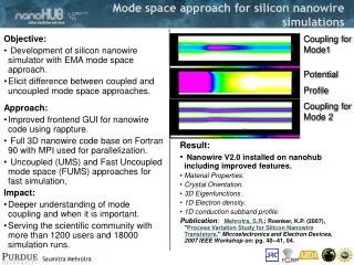
Waveguide Gap. Cold Termination (5-20 K). RF Triplexer. Bolometer Waveguide Mounts. Corrugated Feedhorn. Quartz Low-Pass Filter (2K). Cold JFETS (110 K). SINGLE-MODE MONOLITHIC SILICON BOLOMETERS.

E N D
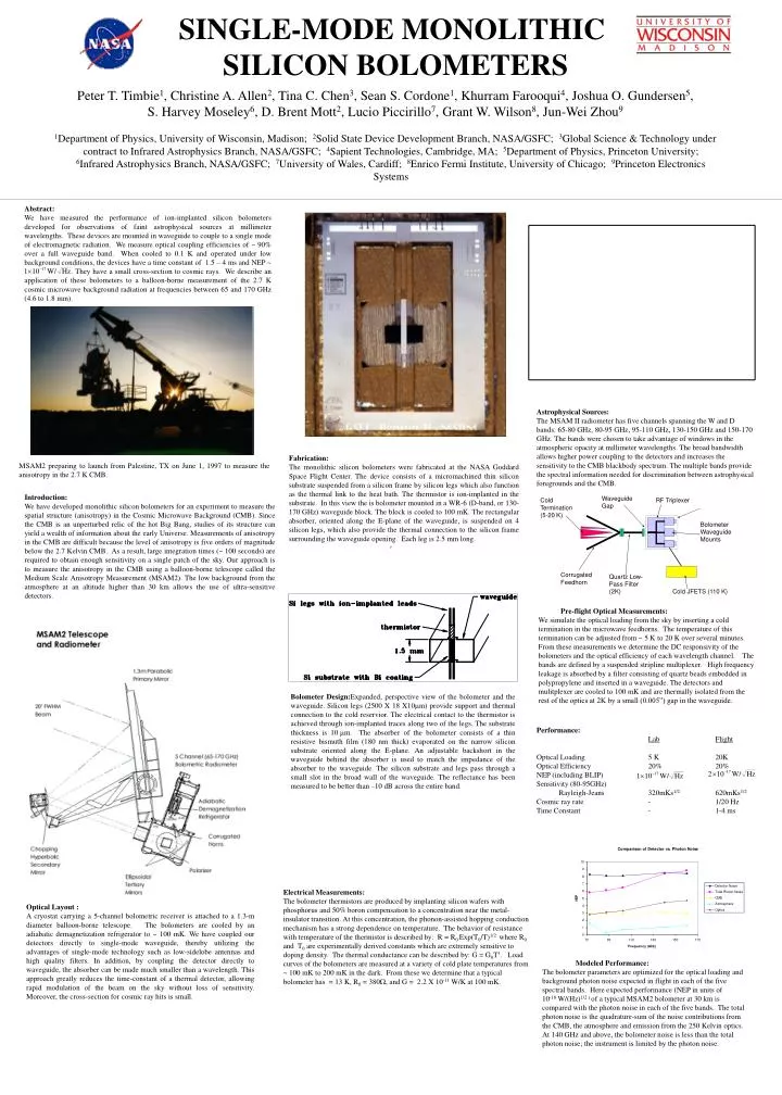
Waveguide Gap Cold Termination (5-20 K) RF Triplexer Bolometer Waveguide Mounts Corrugated Feedhorn Quartz Low-Pass Filter (2K) Cold JFETS (110 K) SINGLE-MODE MONOLITHIC SILICON BOLOMETERS Peter T. Timbie1, Christine A. Allen2, Tina C. Chen3, Sean S. Cordone1, Khurram Farooqui4, Joshua O. Gundersen5, S. Harvey Moseley6, D. Brent Mott2, Lucio Piccirillo7, Grant W. Wilson8, Jun-Wei Zhou9 1Department of Physics, University of Wisconsin, Madison; 2Solid State Device Development Branch, NASA/GSFC; 3Global Science & Technology under contract to Infrared Astrophysics Branch, NASA/GSFC; 4Sapient Technologies, Cambridge, MA; 5Department of Physics, Princeton University; 6Infrared Astrophysics Branch, NASA/GSFC; 7University of Wales, Cardiff; 8Enrico Fermi Institute, University of Chicago; 9Princeton Electronics Systems Abstract: We have measured the performance of ion-implanted silicon bolometers developed for observations of faint astrophysical sources at millimeter wavelengths. These devices are mounted in waveguide to couple to a single mode of electromagnetic radiation. We measure optical coupling efficiencies of ~ 90% over a full waveguide band. When cooled to 0.1 K and operated under low background conditions, the devices have a time constant of 1.5 – 4 ms and NEP ~ . They have a small cross-section to cosmic rays. We describe an application of these bolometers to a balloon-borne measurement of the 2.7 K cosmic microwave background radiation at frequencies between 65 and 170 GHz (4.6 to 1.8 mm). Astrophysical Sources: The MSAM II radiometer has five channels spanning the W and D bands: 65-80 GHz, 80-95 GHz, 95-110 GHz, 130-150 GHz and 150-170 GHz. The bands were chosen to take advantage of windows in the atmospheric opacity at millimeter wavelengths. The broad bandwidth allows higher power coupling to the detectors and increases the sensitivity to the CMB blackbody spectrum. The multiple bands provide the spectral information needed for discrimination between astrophysical foregrounds and the CMB. Fabrication: The monolithic silicon bolometers were fabricated at the NASA Goddard Space Flight Center. The device consists of a micromachined thin silicon substrate suspended from a silicon frame by silicon legs which also function as the thermal link to the heat bath. The thermistor is ion-implanted in the substrate. In this view the is bolometer mounted in a WR-6 (D-band, or 130-170 GHz) waveguide block. The block is cooled to 100 mK. The rectangular absorber, oriented along the E-plane of the waveguide, is suspended on 4 silicon legs, which also provide the thermal connection to the silicon frame surrounding the waveguide opening. Each leg is 2.5 mm long. MSAM2 preparing to launch from Palestine, TX on June 1, 1997 to measure the anisotropy in the 2.7 K CMB. • Introduction: • We have developed monolithic silicon bolometers for an experiment to measure the spatial structure (anisotropy) in the Cosmic Microwave Background (CMB). Since the CMB is an unperturbed relic of the hot Big Bang, studies of its structure can yield a wealth of information about the early Universe. Measurements of anisotropy in the CMB are difficult because the level of anisotropy is five orders of magnitude below the 2.7 Kelvin CMB. As a result, large integration times (~ 100 seconds) are required to obtain enough sensitivity on a single patch of the sky. Our approach is to measure the anisotropy in the CMB using a balloon-borne telescope called the Medium Scale Anisotropy Measurement (MSAM2). The low background from the atmosphere at an altitude higher than 30 km allows the use of ultra-sensitive detectors. • Pre-flight Optical Measurements: • We simulate the optical loading from the sky by inserting a cold termination in the microwave feedhorns. The temperature of this termination can be adjusted from ~ 5 K to 20 K over several minutes. From these measurements we determine the DC responsivity of the bolometers and the optical efficiency of each wavelength channel. The bands are defined by a suspended stripline multiplexer. High frequency leakage is absorbed by a filter consisting of quartz beads embedded in polypropylene and inserted in a waveguide. The detectors and mulitplexer are cooled to 100 mK and are thermally isolated from the rest of the optics at 2K by a small (0.005”) gap in the waveguide. • Bolometer Design:Expanded, perspective view of the bolometer and the waveguide. Silicon legs (2500 X 18 X10m) provide support and thermal connection to the cold reservior. The electrical contact to the thermistor is achieved through ion-implanted traces along two of the legs. The substrate thickness is 10m. The absorber of the bolometer consists of a thin resistive bismuth film (180 nm thick) evaporated on the narrow silicon substrate oriented along the E-plane. An adjustable backshort in the waveguide behind the absorber is used to match the impedance of the absorber to the waveguide. The silicon substrate and legs pass through a small slot in the broad wall of the waveguide. The reflectance has been measured to be better than –10 dB across the entire band. Performance: LabFlight Optical Loading 5 K 20K Optical Efficiency 20% 20% NEP (including BLIP) Sensitivity (80-95GHz) Rayleigh-Jeans 320mKs1/2 620mKs1/2 Cosmic ray rate - 1/20 Hz Time Constant - 1-4 ms Electrical Measurements: The bolometer thermistors are produced by implanting silicon wafers with phosphorus and 50% boron compensation to a concentration near the metal-insulator transition. At this concentration, the phonon-assisted hopping conduction mechanism has a strong dependence on temperature. The behavior of resistance with temperature of the thermistor is described by: R = R0 Exp(T0/T)1/2 where R0 and T0 are experimentally derived constants which are extremely sensitive to doping density. The thermal conductance can be described by: G = G0T3. Load curves of the bolometers are measured at a variety of cold plate temperatures from ~ 100 mK to 200 mK in the dark. From these we determine that a typical bolometer has = 13 K, R0 = 380, and G = 2.2 X 10⁻¹¹ W/K at 100 mK. • Optical Layout : • A cryostat carrying a 5-channel bolometric receiver is attached to a 1.3-m diameter balloon-borne telescope. The bolometers are cooled by an adiabatic demagnetization refrigerator to ~ 100 mK. We have coupled our detectors directly to single-mode waveguide, thereby utilizing the advantages of single-mode technology such as low-sidelobe antennas and high quality filters. In addition, by coupling the detector directly to waveguide, the absorber can be made much smaller than a wavelength. This approach greatly reduces the time-constant of a thermal detector, allowing rapid modulation of the beam on the sky without loss of sensitivity. Moreover, the cross-section for cosmic ray hits is small. • Modeled Performance: • The bolometer parameters are optimized for the optical loading and background photon noise expected in flight in each of the five spectral bands. Here expected performance (NEP in units of 10-18 W/(Hz)1/2 ) of a typical MSAM2 bolometer at 30 km is compared with the photon noise in each of the five bands. The total photon noise is the quadrature-sum of the noise contributions from the CMB, the atmosphere and emission from the 250 Kelvin optics. At 140 GHz and above, the bolometer noise is less than the total photon noise; the instrument is limited by the photon noise.