Download
1 / 16
160 likes | 293 Views
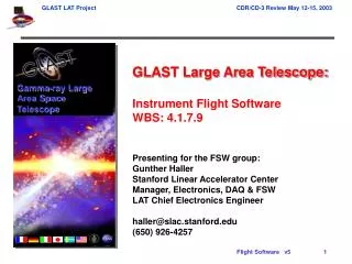
Gamma-ray Large Area Space Telescope. GLAST Large Area Telescope: Mechanical Systems Peer Review March 27, 2003 Section 5.1 – Grid Box Design Marc Campell SLAC Mechanical Systems Mgr. marcc@slac.stanford.edu. Topics. Agenda Key Requirements Design Details Further Work.

E N D
Gamma-ray Large Area Space Telescope GLAST Large Area Telescope: Mechanical Systems Peer Review March 27, 2003 Section 5.1 – Grid Box Design Marc Campell SLAC Mechanical Systems Mgr. marcc@slac.stanford.edu
Topics Agenda • Key Requirements • Design Details • Further Work
Key Mechanical Systems Requirements WC= Will Comply
+Z +Z Grid Box Assembly Design CAL-Grid Interface Mid-Plate X-LAT Plate Assy Radiator Mount Bracket Heat Pipe Patch Panel EMI Shields S/C Mount Interface
X-LAT Plate to E-Box Thermal Joint • Thermal joint must • Carry thermal load of stack of E-Boxes into X-LAT Heat Pipes • Accommodate tolerance stack up E-Box and Grid Box parts • Be repeatable & reliable • Minimize schedule & verification impacts due to removal of X-LAT plates for access to Electronics • Vel-therm gasket material selected • Highly conductive graphite fibers • Mechanically compliant • Meets out-gassing requirement
Midplate to X-LAT Thermal Joint, 2 PLCS, Approx. 60 #6 Fastenerseach side Bolting X-LAT Plate to EMI Shields, Approx. 60 #8 Fasteners per Plate Vel-Therm X-LAT Plate Midplate X-LAT Plate EMI Shields EMI Shields GRID Electronics Stack Cross-Section • 4 cm wide Vel-Therm strip placed around perimeter of each box optimizes conduction vs contact pressure required Note: View along Y-axis
+Z EMI Shield • 6061-T6 AL machining, alodine • Pieces bolted to Grid & each other • Encloses LAT Electronics boxes (EMI tight) • Consists of 4 Radiator Mount Brackets, 4 Heat Pipe Patch Panels, 4 X-side Shields and 4 center Shields • Mechanically supports 3 way heat pipe joint – Downspout, X-LAT and Radiator HP’s • Supports X-LAT plates • Provides mounting for Connecter Patch Plates from Electronics • Provides for venting of enclosure
Radiator Mount Bracket • 6061-T6 Al machining, alodine • Bolts to 3 orthogonal surfaces of Grid corner • Supports & locates Radiators & their Heat Pipes • Supports & locates X-Lat Plates & their Heat Pipes • Provides access to ACD mounting bolts • Supports & locates alignment optics • Provisions for mounting Heater Control Box or Heater Control Connector Bracket for Thermal Control System • Corner lugs for MGSE attachment (sized to carry entire Observatory mass with 2 lugs if required)
Spacecraft Interface Stiffener (Wing) • 6061-T6 machining, alodine • Bolted, pinned & keyed to Grid • Primary function is to spread the point load inputs from the Spacecraft & locally stiffen the Grid against the lateral loads. • Distortions in this area drive the CAL-Grid interface design • Defines Spacecraft interface to LAT (bolted – pinned joint) +Z
Calorimeter to Grid Interface • This interface is part of the Grid stiffness design. • Interleaved CAL baseplate tabs are bolted to –Z surface of Grid • CAL baseplates close-out the Grid structure which increases natural frequency of LAT • Bolted interface applies clamping force over large area (~4223 mm2 per CAL) to develop shear load capability • 2 pins per Grid bay locate CAL and are used to locate hole pattern in Grid and other features such as Tracker cable cut-outs in Grid walls • 54 - #8 + 16 - #6 + 2 – 0.156” dia alignment pins per CAL
Calorimeter to Grid Interface (cont) • Perimeter backing bars engage the outer tabs of the outer CAL’s to double the clamping force on these highly loaded tabs • Additional clamping force can be obtained using 200 ksi bolt material Looking down +Z
Grid • Machined from 10” thick 6061 AL plate • Heat treated to T6 after rough machining • Provides structural backbone for all LAT Subsystems • Provides electrical ground for all LAT Subsystems • Provides thermal path to Radiators for all LAT Subsystems except Electronics boxes (carried by X-LAT plates) • Embedded Heat Pipes in top flange of Grid move heat out • Downspout Heat pipes tie Grid to Radiators • Thermostatically controlled heaters on Grid corners are part of LAT thermal control system • Grid surface is alodine, class 3. Electrically conductive and good surface for adhesive bonding thermal components, harness supports, Tracker cables, MLI supports, EMI tape etc • Integral purge grooves allow for N2 purging of the CAL’s during ground operations
+Z +Z Grid Structure Helicoils for CAL bolts Top Flange Heat Pipes Purge grooves
Work to Close Out Design • CAL-Grid interface under review with GSFC • Finalize design of perimeter backing plate • Investigating making the Spacecraft Interface (Wing) an integral part of the Grid • Finalizing details of Spacecraft mounting w/ Spectrum • Mass & stress optimization of EMI shields and Radiator mount brackets • Radiator mount bracket X axis compliance requirement for differential contraction of Radiators & Grid • Awaiting results of LM thermal analysis • Finalize design implementation of Vel-therm joint
End of Section 5.1