Download
1 / 84
2.43k likes | 5.47k Views
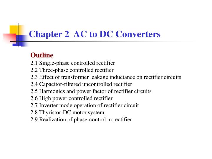
Chapter 2 AC to DC Converters. Outline 2.1 Single-phase controlled rectifier 2.2 Three-phase controlled rectifier 2.3 Effect of transformer leakage inductance on rectifier circuits 2.4 Capacitor-filtered uncontrolled rectifier 2.5 Harmonics and power factor of rectifier circuits

E N D
Chapter 2 AC to DC Converters Outline 2.1 Single-phase controlled rectifier 2.2 Three-phase controlled rectifier 2.3 Effect of transformer leakage inductance on rectifier circuits 2.4 Capacitor-filtered uncontrolled rectifier 2.5 Harmonics and power factor of rectifier circuits 2.6 High power controlled rectifier 2.7 Inverter mode operation of rectifier circuit 2.8 Thyristor-DC motor system 2.9 Realization of phase-control in rectifier
2.1 Single- phase controlled (controllable) rectifier2.1.1 Single-phase half-wave controlled rectifier
Basic thought process of time-domain analysis for power electronic circuits The time- domain behavior of a power electronic circuit is actually the combination of consecutive transients of the different linear circuits when the power semiconductor devices are in different states.
Single- phase half- wave controlled rectifier with freewheeling diode load (L is large enough) Inductive
Maximum forward voltage, maximum reverse voltage Disadvantages: –Only single pulse in one line cycle –DC component in the transformer current
2.1.2 Single- phase bridge fully-controlled rectifier • Resistive load
Average output (rectified) voltage: Average output current: For thyristor: For transformer:
With resistor and inductor When L is large enough, the output voltage and current waveforms are the same as ordinary inductive load. When L is at a critical value
Another single- phase bridge half-controlled rectifier Comparison with previous circuit: –No need for additional freewheeling diode –Isolation is necessary between the drive circuits of the two thyristors
Summary of some important points in analysis When analyzing a thyristor circuit, start from a diode circuit with the same topology. The behavior of the diode circuit is exactly the same as the thyristor circuit when firing angle is 0. A power electronic circuit can be considered as different linear circuits when the power semiconductor devices are in different states. The time- domain behavior of the power electronic circuit is actually the combination of consecutive transients of the different linear circuits. Take different principle when dealing with different load – For resistive load: current waveform of a resistor is the same as the voltage waveform –For inductive load with a large inductor: the inductor current can be considered constant
2.2 Three- phase controlled (controllable) rectifier 2.2.1 Three- phase half- wave controlled rectifier Resistive load, α= 0º
Resistive load, quantitative analysis When α≤ 30º , load current id is continuous. When α > 30º , load current id is discontinuous. Average load current Thyristor voltages
2.2.2 Three- phase bridge fully-controlled rectifier Circuit diagram Common- cathode group and common- anode group of thyristors Numbering of the 6 thyristors indicates the trigger sequence.
Quantitative analysis Average output voltage: For resistive load, When a > 60º, load current id is discontinuous. everage output current (load current): Transformer current:
2.3 Effect of transformer leakage inductance on rectifier circuits In practical, the transformer leakage inductance has to be taken into account. Commutation between thyristors, thus can not happen instantly,but with a commutation process.
Commutation process analysis Circulating current ik during commutation Output voltage during commutation
Quantitative calculation Reduction of average output voltage due to the commutation process Calculation of commutation angle – Id ↑,γ↑ – XB↑, γ↑ – For α ≤ 90۫ , α↓, γ↑
Conclusions –Commutation process actually provides additional working states of the circuit. –di/dt of the thyristor current is reduced. –The average output voltage is reduced. –Positive du/dt – Notching in the AC side voltag
2.4 Capacitor- filtered uncontrolled (uncontrollable) rectifier 2.4.1 Capacitor- filtered single- phase uncontrolled rectifier Single-phase bridge, RC load:
2.4.2 Capacitor- filtered three- phase uncontrolled rectifier Three-phase bridge, RC load
2.5 Harmonics and power factor of rectifier circuits 2.5.1 Basic concepts of harmonics and reactive power For pure sinusoidal waveform For periodic non-sinusoidal waveform where
Harmonics-related specifications Take current harmonics as examples Content of nth harmonics In is the effective (RMS) value of nth harmonics. I1 is the effective (RMS) value of fundamental component. Total harmonic distortion Ih is the total effective (RMS) value of all the harmonic components.
Definition of power and power factor for sinusoidal circuits Active power Reactive power Apparent power Power factor