Download
1 / 26
260 likes | 567 Views
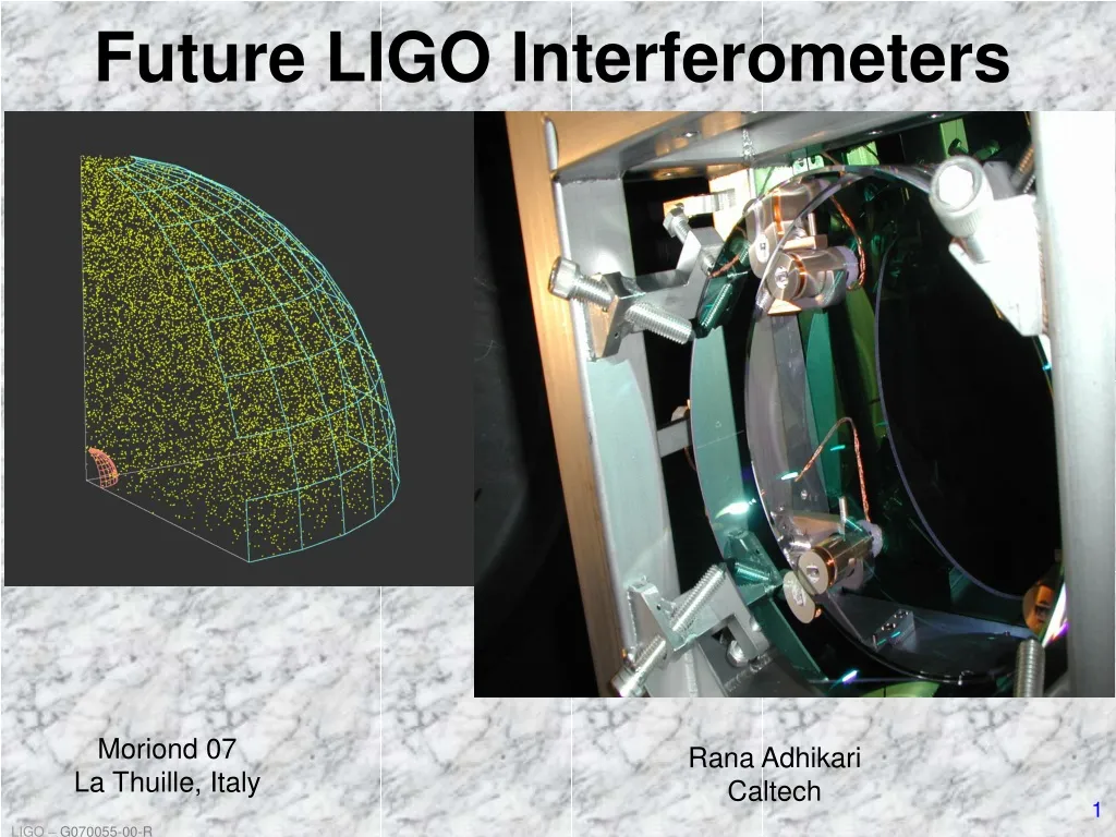
Future LIGO Interferometers. Moriond 07 La Thuille, Italy. Rana Adhikari Caltech. Advanced LIGO. LIGO mission: detect gravitational waves and initiate GW astronomy Next detector Should have assured detectability of known sources

E N D
Future LIGO Interferometers Moriond 07 La Thuille, Italy Rana AdhikariCaltech
Advanced LIGO • LIGO mission: detect gravitational waves and initiate GW astronomy • Next detector • Should have assured detectability of known sources • Should be at the limits of reasonable extrapolations of detector physics and technologies • Must be a realizable, practical, reliable instrument • Daily gravitational wave detections Advanced LIGO Advanced LIGO
The next several years NOW Other interferometers in operation (GEO, Virgo) 4 yrs 4Q ‘06 4Q ‘07 4Q ‘08 4Q ‘09 4Q ‘10 4Q ‘05 Adv LIGO S5 ~2 years S6 • Between now and AdvLIGO, there is some time to improve… • ~Few years of hardware improvements + 1 ½ year of observations. • Factor of ~2.5 in noise, factor of ~10 in event rate. • 3-6 interferometers running in coincidence ! Enhanced LIGO details in “Lessons from LIGO-I” talk on Thursday
ACTIVE SEISMIC ISOLATION FUSED SILICA, MULTIPLE PENDULUM SUSPENSION Advanced LIGO Sketch 40 KG FUSED SILICA TEST MASSES 180 W LASER,MODULATION SYSTEM T ~ 1% PRM Power Recycling Mirror BS Beam Splitter ITM Input Test Mass ETM End Test Mass SRM Signal Recycling Mirror PD Photodiode
10-21 10-22 10-23 10-24 10 Hz 100 Hz 1 kHz Anatomy of the projected Adv LIGO detector performance • Newtonian background,estimate for LIGO sites • Seismic ‘cutoff’ at 10 Hz • Suspension thermal noise • Test mass thermal noise • Unified quantum noise dominates at most frequencies for fullpower, broadband tuning Initial LIGO Advanced LIGO NS-NS Tuning
Advanced LIGO Design Features ACTIVE SEISMIC ISOLATION FUSED SILICA, MULTIPLE PENDULUM SUSPENSION 40 KG FUSED SILICA TEST MASSES 180 W LASER,MODULATION SYSTEM PRM Power Recycling Mirror BS Beam Splitter ITM Input Test Mass ETM End Test Mass SRM Signal Recycling Mirror PD Photodiode
Why use Signal Recycling? no signal recycling Pbs= 10Pbs Principal advantage of signal recycling is in power handling
Ultra Stable Laser • High power laser: 180 Watts Front end high power, injection-locked stage 12 W Master Oscillator 180 W Alternative front end 35 W • Laser power stabilization (relative power fluctuations ~ 2 x 10⁻⁹) • Laser frequency stabilization • Wideband frequency actuation for further stabilization (~ 10-7 Hz/rHz) • Pre-mode cleaner for spatial clean-up and high-frequency filtering Work lead by AEI (Hanover) in collaboration with LZH (Laser Zentrum Hanover)
ACTIVE SEISMIC ISOLATION Test Masses 40 KG SAPPHIRETEST MASSES ACTIVE ISOLATION FUSED SILICA, MULTIPLE PENDULUM SUSPENSION QUAD SILICASUSPENSION 200 W LASER,MODULATION SYSTEM
Core Interferometer Optics Test Masses: 34cm x 20cm 40 kg Large beam size on test masses (6.0cm radius), to reduce thermal noise 40 kg Compensation plates: 34cm x 6.5cm PRM T = 7% BS: 37cm x 6cm Challenges: ITM T = 0.5% Round-trip optical loss: 75 ppm max • Substrate polishing • Dielectric coatings • Metrology • Substrate procurement Recycling Mirrors: 26.5cm x 10cm SRM T = 7%
Substrates • Fused silica: Heraeus (for low absorption) or Corning • Specific grade and absorption depends on optics • ITMs and BS most critical (need low absorption and good homogeneity) • Polishing • Low micro-roughness (< 1 angstrom-rms) • Low residual figure distortion (< 1 nm-rms over central 120mm diameter) • Accurate matching of radii-of-curvature • Surfaces for attachment of suspension fibers • Dielectric coatings • Low absorption (0.5 ppm or smaller) • Low scatter ( < 30 ppm) • Low mechanical loss (< 2e-4) • In-house Metrology • ROC, figure distortion, scattering, absorption Core Optics Compensation Polish before after
Seismic Isolation 40 KG SAPPHIRETEST MASSES ACTIVE ISOLATION COATINGS QUAD SILICASUSPENSION 200 W LASER,MODULATION SYSTEM
Quad Suspensions • Quadruple pendulum: • ~107 attenuation @10 Hz • Controls applied to upper layers; noise filtered from test masses • Seismic isolation and suspension together: • 10-19 m/rtHz at 10 Hz Magnets Electrostatic • Fused silica fiber • Welded to ‘ears’, hydroxy-catalysis bonded to optic
GW Readout 40 KG SAPPHIRETEST MASSES ACTIVE ISOLATION COATINGS QUAD SILICASUSPENSION 200 W LASER,MODULATION SYSTEM
@ the Caltech 40m Lab DC Readout Beamline Controls and Noise Characterization Prototype ELECTRONICS PD MMT1 OMC Tip/Tilt RF PICKOFF MMT2 Squeezer Pickoff
? Projected Noise Sources Initial LIGO Seismic Noise 109 Suspension Thermal Noise 102 Quantum Optical Noise is Tunable!
Measured Transfer Functions from the 40m prototype • ½ MW in the arms -> • ‘Optical Bar’ detector • ~75 Hz unstable opto-mechanical resonance • High Bandwidth servos Optical Spring stiffness ~ 107 N/m Angular spring resonance ~ 2 Hz BMW Z4 ~ 104 N/m Opto-mechanical Spring Radiation pressure: F = 2 P / c Detuned Cavity -> dF/dx
Area proportional to SNR 50 Hz NS/NS Binary Most of the sensitivity comes from a band around 50 Hz
End Test Mass Input Test Mass Laser 125 W Power Recycling mirror 50/50 beam splitter 500 kW 2 kW Signal Recycling mirror GW signal There’s more… Arm Cavity Q Signal Cavity Q
30% Sensitivity Improvement Low laser power! Lower Arm Cavity finesse Lower SRC finesse
Advanced LIGO • Initial instruments, data helping to establish the field of interferometric GW detection • Advanced LIGO promises exciting astrophysics • Substantial progress in R&D, design • Enhanced LIGO starts now!! • Installation in 2011, Data ~2013-2014 • Steady stream of gravitational wave signals