Download
1 / 22
220 likes | 227 Views
phil. Oxford , june 18. Photoinjector at. LAL activities. Brief LAL History. 1955 : fisrt linac at ORSAY 1960 to 1980 : collaborations CERN, Italy, 1967 synchrotron radiation (ACO)

E N D
phil Oxford , june 18 Photoinjector at
Brief LAL History • 1955 : fisrt linac at ORSAY • 1960 to 1980 : collaborations CERN, Italy, 1967 synchrotron radiation (ACO) 1977 DCI e+/e- collsions • 1985 : LAL split in LAL & LURE • 1988 : super ACO (synchrotron radiation) • 2000 : LURE became synchrotron radiation SOLEIL • 2001 : ELYSE (pulsed radiolysis facility) • 2003 : linac of super ACO shut down (dismantlement) • 2005 : PHIL (CARE Project) R&D and building activities Collaborations CERN (CTF), TTF, SLAC (FFTB) A new accelerator at LAL (photoinjector - 9 MeV)
PHIL brief history • 2005 : LAL in CARE project : RF gun for CERN & LAL • 2006 : LASER for PHIL (HQ Laser) • 2007 : start of installation in old LINAC building (building modifications, bunker build up,…) • 2008 : ASN deadline for PHIL PHIL start ok • 2009 : fisrt beam ?
PHIL Goals • Developpement of electrons sources & associated technologies • Provide electron beam for different users • Formation (students, thesis,…) • Maintain & improve know-how@LAL for future accelarator projects • New accelerator in LAL/Orsay
Possible applications TEST BENCH FOR: • RF technology and high brillance guns design • New Cathodes • High gradient structures • Low energy diagnostics • Simulations code • Laser pulse shaping • … USERS • Detector calibration (charge ,energy) • Chemistry reactions • Plasma acceleration with external injection • …
Photoinjector principle F = q Ef RF (EM wave) Acceleration of charged particle Laser beam Electron beam Ef Copper pillbox cavity Temporal structure are identical Standing wave with on axis Electric field short duration electron bunch (ps or below) Electron production with photoemission (cathode inside cavity) Ef ~ 80 MV/m leads to E ~ 4 MeV in 10 cm (3GHz)
Photoinjector parts • Photon source : laser Nd:YLF • Electron source : RF gun + photocathode • RF source : electric field for acceleration • Transport line : beam properties caracterization (size, duration, charge,…) 5. Status & Planning
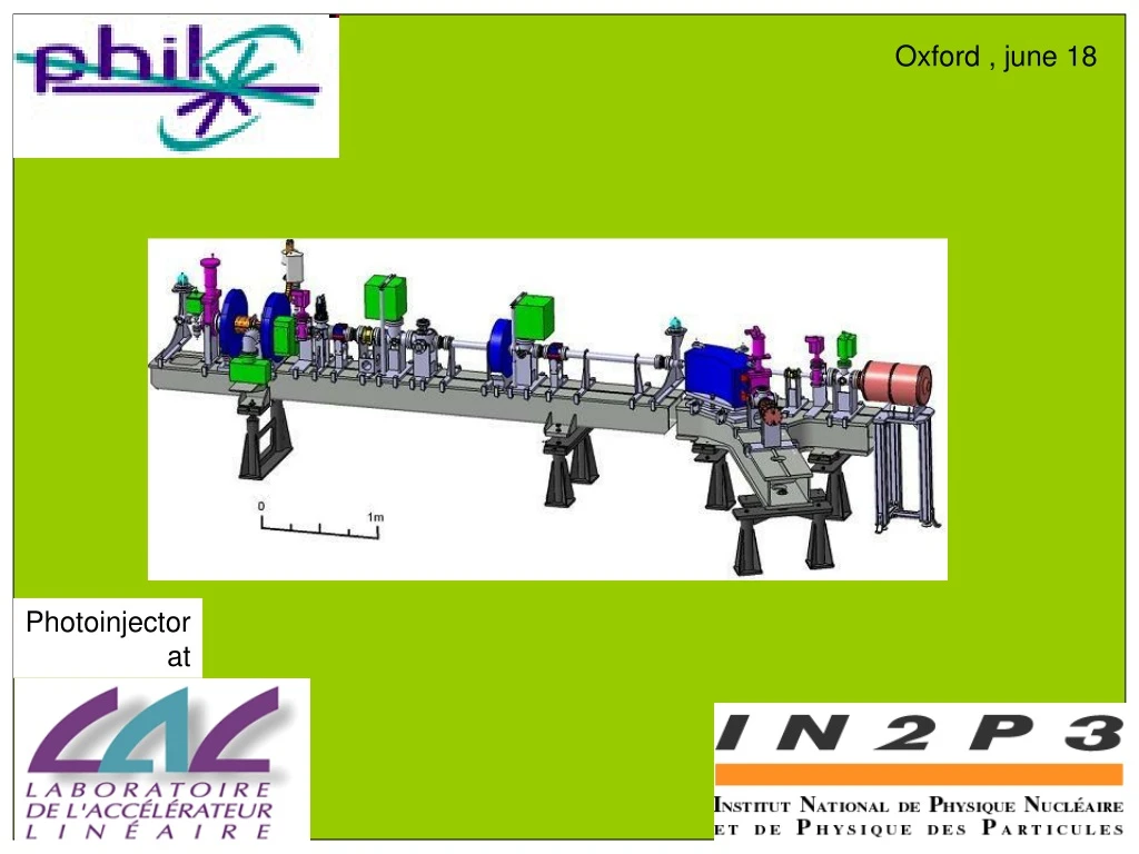
PHIL installation photon source 2.5 m RF source User area electron source
PHIL laser Photon source Oscillator Nd-YLF F= 74,963750MHz W/impulsion: 2 nJ X 2 1 mJ Amplification Nd-YLF gain ~ 106 80 µJ Pockels cell X 2 Bought from HQ Laser in 2006
Photon source Laser transport Upper view Accelerator room 1.5 m laser room 80 µJ/pulse laser 2 m • = 266 nm F = 5 Hz 50 µJ/pulse Virtual cathode Streak camera RF gun cathode Length of transport ~ 17 m Laser position stabilisation
PHIL RF gun Electron source HFSS simulations F = 3 GHz, 2.5 cell RF gun for CERN/CLIC 20 mm
Photocathode Electron source • Start with copper ~ 100 pC • CsTe cathode ~ 4 nC • transfert arm Project with CERN • - Other types of photocathodes ? • Versatility of injector : • - high level detection signal • - low emittance • - short pulses Q Te = 20 nm Cs = 16 nm Cs2Te photocathode CsTe QE ~ 8% fabrication QE ~ 1 % after few hours of RF (co-evaporation is better) Life time ~ several months Detail of Transfert arm
RF source RF source COUPLER 6 dB CIRCULATOR Pik Prk SF6 Pic pump Prc pump Low level Input 140 W – 3 µs THALES Klystron (2040 type – 2001) Pmax = 20 MW (230 kV – 250 A) Gain ~ 52% RF GUN KLYSTRON MODULATOR RF duration = 3 µs
RF transport RF source COUPLER 6 dB CIRCULATOR Pik Prk SF6 Pic pump Prc pump PA BOOSTER RF GUN KLYSTRON MODULATOR
1 m PHIL beam transport line RF input booster emittance screen pump RF gun BPM WCM Vacuum valve laser Beam catcher slit solenoids 60° dipole Cerenkov Fisrt version
Beam caracteristics Fisrt version of accelerator
Project status V0 15/06/09 klystron July 2008 BPM Leaks ! march 2009 Reparation installation Pelletier copper Tests ok. Not installed Regulation T°C E = 5 MeV Q = 100 pC F = 5 Hz
Thank you for your attention 18/06/09 H. Monard monard@in2p3.lal.fr