Download
1 / 10
100 likes | 475 Views
Projects 1: Project Kickoff Meeting Project: Design an Interface between a Robot and a LTU Laptop Group members: Colin Black Steve Holcomb Objective Design and implement an interface between a robot and a LTU laptop Target Goals:

E N D
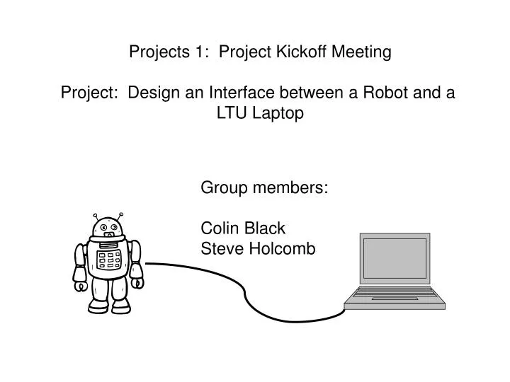
Projects 1: Project Kickoff Meeting Project: Design an Interface between a Robot and a LTU Laptop Group members: Colin Black Steve Holcomb
Objective • Design and implement an interface between a robot and a LTU laptop
Target Goals: • Robot should be able to traverse forwards and backwards with the capability to turn • Robot should be able to travel at two to three speeds • Interface should be easily available for use in third-party programs • i.e. writing maze-traversal programs
Design Sub-Systems Power System Drive System Steering System Sensor System Laptop Interface
Power Sub-System • Capable of powering interface and robot • Laptop runs on batteries • Power sources under consideration: • Batteries • Heavy • Limited functional time • 110V connection to maze exterior • Limits size of maze • Requires addition of transformer on robot
Drive Sub-System • A single drive wheel located at the rear of the robot • Variable speed bi-directional motor • Controlled through interface board • Tachometer connected to drive wheel for distance/speed reporting to interface
Steering Sub-System • Based on standard Rack and Pinion design • Single servo/motor to control steering angle • Angle controlled through interface board
Sensor systems • Initial sensor type: touch • Sensor contact causes immediate event/interrupt; drive halted • Expansion of system possible to include other sensor types
Laptop Interface • Use of Handyboard to relay commands to drive/steering sub-systems and contact data from sensor sub-system • Laptop interfaces to Handyboard through Parallel/Serial port • Interface to third-party programs through binary API or compile-time headers • Knowledge of Windows 2k/XP Device Drivers required
Timeline • Parts ordered by 11/30 • Drive system/chassis built 02/01 • Steering system built 02/15 • Sensor/Interface built 03/01 • Device Drivers/Headers written 03/08 • Final testing 03/29 • (Competition date - RoboFest) 04/27