Download
1 / 32
330 likes | 544 Views
The Virgo detector: status and first experimental results. Nicolas Arnaud CERN EP Seminar 17/03/2003. Outline. The quest for gravitational waves ( GW ): a long history Detection principles Interferometric detectors Description of the Virgo interferometer Optical scheme

E N D
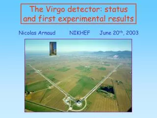
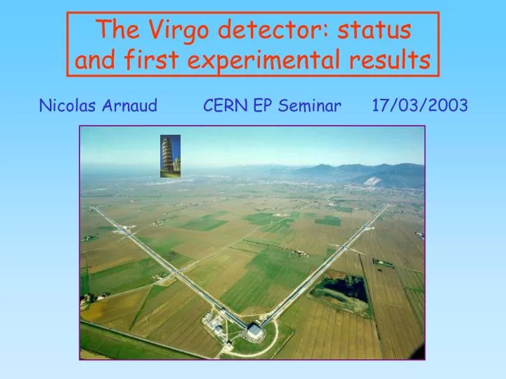
The Virgo detector: status and first experimental results Nicolas Arnaud CERN EP Seminar 17/03/2003
Outline • The quest for gravitational waves (GW): a long history • Detection principles • Interferometric detectors • Description of the Virgo interferometer • Optical scheme • Main features of the instrument • Foreseen sensitivity • Experimental control of the Central Interferometer (CITF) • CITF description and CITF commissioning goals • Experimental results (spring 2001 summer 2002) • Main GW sources and filtering techniques • Virgo versus the other GW interferometric detectors • The LIGO interferometers (USA) + TAMA (Japan)
Gravitational waves: a brief history • First «imagined» by Poincaré in 1905 «J'ai été d'abord conduit à supposer que la propagation de la gravitation n'est pas instantanée mais se fait à la vitesse de la lumière (…) Quand nous parlerons donc de la position ou de la vitesse du corps attirant, il s'agira de cette position ou de cette vitesse à l'instant où l'onde gravifique est partie de ce corps (…)» [Italics of the author] • GW existence predicted by Einstein in 1918 • Direct consequence of the General Relativity (1915) • But not immediately accepted: • GW appear after a linearization of the Einstein equations • while non-linearity is the key of their physical content • Non linear correction terms cannot be calculated this way «GW travel at the speed of mind » Sir A.S. Eddington • Theoretical framework developped in the 50’s and 60’s • (Pirani & Isaacson) • Indirect evidence of the GW existence:PSR 1913+16 • Hulse & Taylor(Nobel Prize 1993) [& Damour] GW must exist !
GW amplitude: L L + DL Gravitational waves main characteristics • Perturbations of the Minkowski metric propagating at the speed of light • Quadrupolar emission • Extremely weak!!! Ex:Jupiter radiates 5.3 kW as GW during its orbital motion • over 1010 years:EGW = 2 1021 J Ekinetic 2 1035 J • A good source of GW must be: asymetric, compact, relativistic Luminosity G/c5 10-53 W-1 No Hertz experiment possible! GW effect : differential modification of lengths Detectors:IFO, resonant bars, LISA… Detections expected up to the Virgo cluster (~ 20 Mpc)
Interferometric detection Suspended Michelson Interferometer Mirrors used as test masses Variation of the power Pdet at the IFO output port Optical path modification Incident GW Sensitivity :
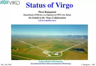
The Virgo Interferometer • French-Italian collaboration • (CNRS/INFN) • ~ 50 physicists • ~ 50 engineers • Budget: ~ 75 M€ • 55% Italy, 45% France Site: Cascina, near Pisa • Planning: • Spring 2001 - Summer 2002: successfully • Central Interferometer Commissioning completed • 2003:Shutdown and transition to the full detector • From summer 2003:Full scale Virgo commissioning • First Physical Data foreseen for2004 … or later
White fringe 10-17 The Virgo Detector Laser power: Pin = 20 W Sensitivity Gain : 3000 30 ~ 106 Laser Sensitivity : hsens ~ 3 10-21 10-23 10-22 Detection Photodiode To increase the arm length : 1 m 3 km To add Fabry-Perot cavities (Finesse = 50 Gain = 30) To add a recycling mirror (P = 1 kW on the Beam Splitter)
The Virgo SuperAttenuator INFN Pisa Length ~ 7 m; Mass ~ 1 ton Structure in inverted pendulum - fres ~ 30 mHz • Dual role: • Passive seismic isolation • Mirror active control • only 0.4 N needed • for a 1 cm motion Seismic Attenuation: ~ 1014 à 10 Hz
Full Virgo configuration Virgo configuration
Thermal noise mirrors Violin modes Thermal noise Tail of the 0.6 Hz marionetta/ mirror resonance Shot noise «Seismic Wall» Minimum ~3 10-23between ~ 500 Hz et 1 kHz Virgo foreseen sensitivity
CITF commissioning = 1rst step of Virgo commissioning • Recycled and suspendedMichelson Interferometer • Uses the main technology developped for Virgo • CITF commissioning goals: • check the different component performances • validate control algorithms • test data management (acquisition, storage…) «West» Mirror Arm lengths ~ 6 m Recycling Mirror «North» Mirror The CITF is not sensitive enough: no hope to collect data with GW signal!!! Virgo central interferometer (CITF)
Very narrow Working Point In addition: residual low frequency motion of mirrors (0.6 Hz) CITF active controls needed (local and global) Longitudinal control «Locking » Resonant cavities dl ~ 10-10 – 10-11 m Angular control «Alignment » Aligned mirrors dq ~10-9 – 10-7 rad Goal : CITF and working point • Best sensitivity : • Michelson on dark fringe control arm asymmetry:l2-l1 • Recycling cavity resonant (maximize the stored power) • control IFO mean length:l0 + (l1+l2)/2
The steps of the Virgo control Control aim: to go from an initial situation with random mirror motions to the Virgo working point Virgo frame • Decreasing the residual motion • separately for each mirror • Local controls • + First alignment of mirrors • Lock acquisition of the cavities • Check working point control stability • Switch on the angular control • Automatic Alignment Switching from local controls to global controls
Fringe Counting Fringe interval ~ 0.5 mm Global Control Time (s) AC Power Error signal Time (s) DC Power Interferometer power output Dark fringe June 13th 2001 Time (s) First control of the Michelson
Stored Power • Pmax ~ 5.8 W • Gain ~ 70 • (Plaser ~ 80 mW) • Dark fringe • less «dark» • unperfect contrast • Large fluctuations of • the stored power: • low feedback gain • misalignments December 16th 2001 IFO output power D5 Recycling correction West correction • Recycling : D5 photodiode • Signal reflected by the Beam Splitter 2nd face (AR coating) Correction applied on the Recycling Mirror First control of the recycled CITF • A complex problem: • Two lengths to be controlled instead of one • coupled error signals • Narrow resonance of the recycling cavity (high finesse) • Limited force available to act on mirrors • Error signal ~ to the electronic noise outside resonance • [weak laser power + Recycling mirror reflectivity = 98.5%] • Main issues: • To select the right resonance • [trigger on the stored power] • Simultaneous acquisition of the 2 cavity controls • Fast damping of the 0.6 Hz pendulum resonance excited • each time the locking attempt fails
CITF Main steps • 5 ER for the CITF commissioning • 3 days duration (24h/24h) • ~ 1 TB data collected / ER • ~ 5 MBytes/s ~ 160 TB/an • The 2 first in Michelson configuration (9/01 and 12/01) • The 3 others Recycled configuration (4/02, 5/02 and 7/02) All sources of control losses understood Improvements already done or in progress • Main CITF improvements: • Suspension hierarchical control (feedback splitting) • Output Mode-Cleaner locking • Laser frequency stabilization above few Hz • West mirror linear alignment
June 2001 July 2002 Factor 103 improvement @ 10 Hz Factor 105 improvement @ 1 kHz Readout electronic noise Back scattered light on laser bench Alignment Noise: peaks = qx resonances Auxiliary laser frequency noise Room for many more Improvements Laser frequency noise due to vibrations of the input Mode-Cleaner length Laser frequency noise + some test masses resonant modes CITF sensitivity improvements
From the CITF to the full Virgo (1) • Question:what does the CITF teach us on the full Virgo? • Answer:many (encouraging) things but the commissioning • of the complete Virgo remains a major challenge • Main results of the CITF commissioning: • Scientific program completed • The different parts of the control chain work well • seismic noise no more dominant above 1 Hz • methods for resonance acquisition developped • linear feedbacks (z and q) stable on large timescales • Dark fringe control @ 10-12 m as requested for Virgo • Large improvements in sensitivity in only one year • Gain in ‘experimental experience’ allows one to prepare • several upgrades for the full Virgo in various systems • Main concerns:input laser system • CITF studies are direct benefits for Virgo
From the CITF to the full Virgo (2) • CITF Virgo will provide ‘free’ sensitivity improvements: • Arm length:6 m 3 km gain of a factor 500 in h • Fabry-Perot cavities: factor 30 in addition • In reality, such gains are unfortunately not automatic: • some noises do not depend on the laser optical path • as soon as the main noise in a given bandwidth is lowered, other sources previously hidden appear! • Virgo optical scheme more complicated (4 lengths) • Dark Fringe (difference in the arm lengths) • Recycling Length (mean length of the interferometer) • 2 Fabry-Perot cavities • Lock acquisition procedure from CITF methods • more complex • currently under study with simulations • Virgo can benefit from the other detector experiences
« As a first conclusion, the tube is straight! » First beam in the 3 km North arm Thursday March 13th 2003: First beam travelling in the 3km North Arm!!! LAST MINUTE
Preparing the GW Data Analysis • Activity parallel to the experimental work on detectors • 1 international conference / year (GWDAW) • Large number of potential GW sources: • compact binary coalescences (PSR 1913+16) • black holes • supernovae • pulsars • stochastic backgrounds • … • The corresponding signals have very different features • various data analysis techniques • Brief review of the main GW signals and methods
Chirp signal: amplitude and frequency increase with time until the final coalescence • The signal knowledge ends • before the coalescence • when approximations used • for the computation are • no more valid. • large theoretical work to go beyond this limit! Waveform analytically estimated by developments in v/c Wiener (optimal) filtering used for data analysis Compact binary coalescences
Impulsive sources (‘bursts’) • Examples: • Merging phase of binaries • Supernovae • Black hole ringdowns • GW main characteristics: • Poorly predicted waveforms • model dependent • Short duration (~ ms) • Weak amplitudes Zwerger / Müller examples of simulated supernova GW signals • Need to develop filters : • robust (efficient for a large class of signals) • sub-optimal (/ Wiener filtering) • online (first level of event selection)
Pulsars • GW signal:permanent, sinusoidal, possibly 2 harmonics • Weak amplitude detection limited to the galaxy • Matched filtering-like algorithms using FFT periodograms • Idea:follow the pulsar freq. on large timescales (~ months) • compensation of frequency shifts: Doppler effect • due to Earth motion, spindown… • Very large computing power needed (~ 1012 Tflops or more) • Hierarchical methods are being developped 1 TFlop • Need to define the better strategy: • search only in the Galactic plane, area rich of pulsars • uniform search in the sky not to miss close sources • focus on known pulsars • Permanent signal coincident search in a single detector: compare candidates selected in 2 different time periods
Stochastic backgrounds • Described by an energy density per unit logarithmic • frequency normalized to the critical density of the universe: • Two main origins: • Cosmological • Emission just after the Big Bang: ~10-44 s, T~1019 GeV • Detection informations on the early universe • Astrophysical • Incoherent superposition of GW of a given type emitted • by sources too weak to be detected separately. • Detection requires correlations between 2 detectors • After 1 year integration: h02stoch 10-7 (1rst generation) • 10-11 (2nd generation) • Theoretical predictions: ~ 10-13 10-6 • Current best limit:stoch 60 @ 907 Hz [Explorer/Nautilus] with
Coincidence detections • Why ? • Some detectors • will be working • in the future • LIGO : 4 km • VIRGO : 3 km • GEO : 600 m • TAMA : 300 m • ACIGA : 500 m • Coincidence = only way to separate a real GW from • transient noises in a particular interferometer • Coincidences may allow to locate the source position in sky • Coïncidences with other emissions: g, n now ACIGA
Interferometer angular response The detectable GW amplitude is a linear combinationof the two GW polarizations h+ et h h(t) = F+ h+(t) + F h(t) Declination d Beam Pattern statistical distribution Angular response RMS ~ 0.45 Right ascension a • 2 maxima ( detector) • 4 minima (blind detector) Reduction of a factor ~ 2 in average of the amplitude
Example of the Virgo-LIGO network • Spatial responses • in a given direction • Similarities between • the maps of the two • LIGO interferometers • Complementarity • Virgo / LIGO • Good coverage of • the whole sky • Double or triple coincidences unlikely
Virgo versus other interferometers 10-7 October-November 2002 June-August 2002 10-12 LIGO TAMA 10-20 10-20 1 Hz 10 Hz 10 kHz 10 kHz 10-7 • All sensitivities in m/Hz • Comparable plots! • Improvements still needed! • Record sensitivity:Tama • 10-18 m/Hz @ 1 kHz • @ 10 Hz, the CITF has the • best sensitivity: 10-13 m/Hz Virgo CITF July 2002 10-20 5 kHz 1 Hz
Summary • Many interferometers are currently under developpement • Worldwide network in the future • All instruments work already although they did not prove yet there can fulfill their requirements • Control of complex optical schemes with suspended mirrors • All sensitivities need to be significally improved to • reach the amplitude of GW theoretical predictions • Many different GW sources • various data analysis methods in preparation • In the two last years, the Virgo experiment became real • The different parts of the experiment work well together • Successful commissioning of the CITF • 2003: CITF Full Virgo • First ‘physically interesting’ data expected for 2004 !?!?!
GW: a never ending story The future of gravitational astronomy looks bright. 1972 That the quest ultimately will succeed seems almost assured. The only question is when, and with how much further effort. 1983 [I]nterferometers should detect the first waves in 2001 or several years thereafter (…) 1995 Km-scale laser interferometers are now coming on-line, and it seems very likely that they will detect mergers of compact binaries within the next 7 years, and possibly much sooner. 2002 Kip S. Thorne
References about Virgo and GW • Virgo web site: www.virgo.infn.it • Virgo-LAL web site (burst sources): www.lal.in2p3.fr • Source review: (recent) • C. Cutler - K.S. Thorne, gr-qc/0204090 • Supernova signal simulation: • H. Dimmelmeier et al.astro-ph/0204288 and 89 (2002) • Some other GW experiment websites: • LIGO: www.ligo.caltech.edu • GEO: www.geo600.uni-hannover.de • TAMA: www.tamago.mtk.nao.ac.jp/tama.html • IGEC (bar network): igec.lnl.infn.it • LISA: sci.esa.int/home/lisa