Download
1 / 18
200 likes | 364 Views
Klystrons and RF Feed. A. Moretti March 15 , 2005. Outline. Klystrons for the Proton Driver 325 MHz RF Distribution Layout and description 1300 MHz RF Distribution Layout and description Conclusion. Layout of 0.5 MW Initial Linac. Klystrons. The 8 GeV Linac uses 12 Klystrons of 2 Types

E N D
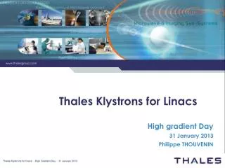
Klystrons and RF Feed A. Moretti March 15 , 2005
Outline • Klystrons for the Proton Driver • 325 MHz RF Distribution Layout and description • 1300 MHz RF Distribution Layout and description • Conclusion A. Moretti - Proton Driver Director's Review
Layout of 0.5 MW Initial Linac A. Moretti - Proton Driver Director's Review
Klystrons • The 8 GeV Linac uses 12 Klystrons of 2 Types • 325 MHz JPARC Klystron (1-2 required for front end) • 1300 MHz TESLA Multi-Beam Klystron (11 required) • Both types are now “Catalog Items” A. Moretti - Proton Driver Director's Review
Toshiba E374A High Power Amplifier Klystron Tube is designed for particle Accelerators Tube tunable to 325 MHz: Tube is in production for J-Parc; 17 tubes have recently been delivered to J-Parc. Power Output = 3.0 MW Gain = 50 dB Efficiency = 55 % Duty Factor = 2.6% Toshiba has verified to us that tube can meet Baseline Specification of 4.5 ms at 2.5 Hz and future requirement of 1.5 m.s 10 Hz A. Moretti - Proton Driver Director's Review
MBK: Three Klystron Vendors • Thales: Prototype in operation at DESY for 18,000’s hrs., 2 sent back because of gun sparks-3000 hrs ; They have been modified and corrected, sent back, met Spec at factory and no hint of problem at DESY. DESY has ordered 8 more tubes. Cathode emission loading high compared to other vendors predicted life of 40,000 hrs. Looking at different dispenser Cathode materials for longer life. • CPI: One tube has been shipped to DESY, Testing limited to 9 MW full duty because of limitation factory PS, 58 % efficiency measured, study underway to increase efficiency, cathode Loading for long life is low, tube has large Diameter. • Toshiba: R&D phase has been tested to 10.3 MW , 1 ms at 10 Hz needs PS modification full pulse flattop length, low cathode Loading for long life. A. Moretti - Proton Driver Director's Review
Multi Beam Klystron THALES TH1801 Thales has verified to us that tube can meet Baseline Specification of 4.5 ms at 2.5 Hz and future requirement of 1.5 m.s 10 Hz. A. Moretti - Proton Driver Director's Review
CPI VKL-8301 MBK A. Moretti - Proton Driver Director's Review
Toshiba E3736 MBK A. Moretti - Proton Driver Director's Review
Klystron Pulse Width • The “Initial” Proton Driver scenario requires a 4.5 msec RF pulse (3 msec beam pulse) at 2.5 Hz • Both Klystron manufacturers will deliver tubes to this pulse width, but cannot test this at the factory. • The 4.5 msec modulator being built for PD at SMTF will be used for this test. A. Moretti - Proton Driver Director's Review
1300 MHz RF Fanout • Fanout is nearly a copy of 36:1 TESLA RF fanout • Phase shifters used below ~2 GeV • Components rated to handle Ultimate beam power A. Moretti - Proton Driver Director's Review
RF distribution 1300 MHz (Typical) LL RF Drive Signal Input 10 MW Klystron Hybrid Coupler Circulator Load Only used in the R&D Phase IQM Ferrite modulator Phase & Amplitude One of 18 Cavities in Cryo Module A. Moretti - Proton Driver Director's Review
4 port Hybrid Ferrite RF Distribution 325 MHz (Typical) Only used in the R&D Phase To one of the 71 cavities in the 110 MeV accelerator Hybrid Coupler 325MHz Klystron Circulator Load IQM Ferrite Modulator Phase & Amplitude Cavity A. Moretti - Proton Driver Director's Review
Waveguide components near 1300 MHz Klystron at A0 Typical Components 5 MW at Output of the A0 High Power Klystron: Right Angle Bend Straight Piece Flex Section Directional Coupler A. Moretti - Proton Driver Director's Review
Typical Waveguide 1300MHz in A0 1300 MHz Coaxial Load Waveguide Load 4 port Circulator 325 MHz Components Available many Vendors. A. Moretti - Proton Driver Director's Review
High Power Components 1300 & 325 MHz • 5 MW Circulator: Many vendors, Not used in the XFEL design More Vendors Available for lower Power Circulators. • Hybrid Coupler: Many vendors available High and low power, may require optimization for better specs in VSWR, etc. • Loads: Many vendors available High and low power. • Other components: Many vendors available High and low power. • IQM: Vendor delivery in 2 months, High power, 1300 MHz. In House: High and Low power @ 1300 & 325 MHz. A. Moretti - Proton Driver Director's Review
CONCLUSIONS • Components are commercially available from many Vendors to meet our requirements in a timely manner to complete the system as designed. • The only new component, the IQM for Phase and Amplitude control, is being developed both In-House & Commercially. (see Terechkine’s talk) • The SMTF is a test bed for all the components and system; will be used to test all components and qualify Vendors. A. Moretti - Proton Driver Director's Review