Download
1 / 10
100 likes | 247 Views
MICE LH2 Absorber Safety. Mary Anne Cummings Edgar Black (IIT) Abingdon, UK Oct. 30, 2003. Design considerations. Multiple scattering. x. x. P 2. P 1. q 2. q 1. q 1. P 1. accelerator. q 1. accelerator. z. z. RF cavity. RF cavity. absorber. absorber.

E N D
MICE LH2 Absorber Safety Mary Anne Cummings Edgar Black (IIT) Abingdon, UK Oct. 30, 2003
Design considerations Multiple scattering x x P2 P1 q2 q1 q1 P1 accelerator q1 accelerator z z RF cavity RF cavity absorber absorber Muons through matter can actually focus! cooling heating • Emittance eqn: • So, minimizing beam heating term by minimizing and maximizingLR.The design features of a cooling channel: • Hydrogen (lowest Z, highest LR) for the cooling medium. • Thin windows for the hydrogen absorbers. • LH2 absorbers placed in large magnetic fields. • additionally… • 4) RF between LH2 absorbers to restore forward momentum: q2
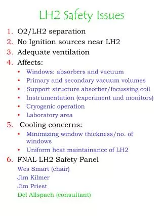
Liquid Hydrogen Safety • For safe operation, have designed with the redundant requirements: • LH2 and O2 separation • The avoidance of any possible ignition sources in the vicinity of the hydrogen. • The four key features of the design with respect to safety are: • The window thicknesses specified based on safety factors of 4.0 for the absorber window and 2.5 for the vacuum window at maximum allowable working pressure (MAWP). • An argon-gas-filled jacket surrounding the vacuum chambers of the RF/coupling magnet modules and the hydrogen absorber/focusing magnet modules to minimize the possibility of oxygen leaking in and freezing on the absorber-system windows. • Separate vacuum volumes provided for the RF cavities, magnets, and LH2 absorbers. • Hydrogen evacuation systems using valved vents into external buffer tanks.
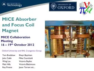
MICE Cooling Channel Design • Other safety concerns: • Magnet quenching, LH2 absorber stability • Any instrumentation must be “instrinsically safe” • Sufficient shielding from detectors/RF • Robust, simple failsafe systems Compact environment
Absorber/Coil Assembly • Sufficient venting into evacuation tank • Secure plumbing attachments • Stable and repeatable placement of LH2 absorber inside magnet bore
Experiment Installation Coil LH2 absorber • Accessibility in a compact, sealed environment • Certification of Windows-Absorber-Coil Assembly • Accurate component placement Hydrogen storage ISSUES:
LH2 Window R & D Photogrammetry: Non-contact measurement of strain by calculating displacement Strain gages ~ 20 “points” Shape measurement at FNAL Pressure tests at NIU Photogrammetry ~1000 points
Window # Test temp. FEA results Test results Minimum window thickness (mm) Rupture pressure (psi) Window thickness from CMM (mm) Measured rupture pressure (psi) 1 293K 0.13 48 0.114 42 2 293K 0.33 117 0.33 119 3 293K 0.345 123 0.345 120 4 80K 0.33 156 0.33* 152 2. 3. 4. Absorber window test results 4 burst tests: 1. Cryo test Performance measurement (photogrammetry) 1. Room temp test: pressurize to burst ~ 4 X MAWP (25 psi) 2. Cryo test: a) pressure to below elastic limit to confirm consistency with FEA results b) pressure to burst (LN2 temp) ~ 5 X MAWP fromASME:UG 101 II.C.3.b.(i) Discrepancies between photogrammetry and FEA predictions are < 5%
Certification procedures • Windows to be tested/certified independently: both vacuum and absorber • Pressure tests of assembled absorber manifold • Assembly inside vacuum containment vessel or magnet bore • Survey of absorber position inside magnet • Cryo pressure test after absorber installation • Pressure test of vacuum vessel after installation • Nitrogen/argon purge of absorber and vacuum before LH2 fill and vacuum area evacuation. • Safety valve tests
FNAL Requirements: • Burst test 5 vacuum windows at room temp. to demonstrate a burst pressure of at least 75 psid (~5 bars) for all samples. (pressure exerted on interior side of vacuum volume). • Non-destructive tests at room temperature: • External pressure to 25 psid (~1.7 bars) to demonstrate no failures: no creeping, yielding, elastic collapse/buckling or rupture • Other absorber vacuum jacket testing to ensure its integrity Vacuum Windows Vacuum “bellows” window (34 cm diam): No buckling at 1st yield (34 psi) Internal pressure: burst at 83 psi