Download
1 / 56
560 likes | 582 Views
Advanced Gravitational-wave Detector Technologies. Future generations of instruments. Nergis Mavalvala GR-17 July 2004. GW interferometer at a glance. L ~ 4 km For h ~ 10 –21 D L ~ 10 -18 m. Seismic motion -- ground motion due to natural and anthropogenic sources. Thermal noise --

E N D
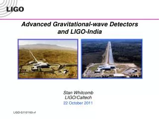
Advanced Gravitational-wave Detector Technologies Future generations of instruments Nergis MavalvalaGR-17July 2004
GW interferometer at a glance L ~ 4 km For h ~ 10–21 DL ~ 10-18 m Seismic motion -- ground motion due to natural and anthropogenic sources Thermal noise -- vibrations due to finite temperature Shot noise -- quantum fluctuations in the number of photons detected
Initial LIGO Sensitivity Goal • Strain sensitivity < 3x10-23 1/Hz1/2at 200 Hz • Displacement Noise • Seismic motion • Thermal Noise • Radiation Pressure • Sensing Noise • Photon Shot Noise • Residual Gas • Facilities limits much lower
S2 2nd Science Run Feb - Apr 03 (59 days) S1 1st Science Run Sept 02 (17 days) Strain (1/rtHz) LIGO Target Sensitivity S3 3rd Science Run Nov 03 – Jan 04 (70 days) Frequency (Hz) Science Runs and Sensitivity DL = strain x 4000 m 10-18 m rms
Why a better detector? Astrophysics • Factor 10 to 15 better amplitude sensitivity • (Reach)3 = rate • Factor 4 lower frequency bound • NS Binaries • Initial LIGO: ~20 Mpc • Adv LIGO: ~350 Mpc • BH Binaries • Initial LIGO: 10 Mo, 100 Mpc • Adv LIGO : 50 Mo, z=2 • Stochastic background • Initial LIGO: ~3e-6 • Adv LIGO ~3e-9
10-21 10-22 10-23 10-24 10 Hz 100 Hz 1 kHz Advanced LIGO Target Sensitivity • Newtonian background • Seismic ‘cutoff’ at 10 Hz • Suspension thermal noise • Test mass thermal noise • Optical noise Initial LIGO Advanced LIGO
The Target Build a detector limited by fundamental noise sources Gravity gradients at low f Quantum noise at high f The Strategies Seismic noise reduced 40x at 10 Hz Thermal noise reduced 15x Optical noise reduced 10x The Challenges... and overcoming them Rest of this talk... Quantum LIGO Advanced LIGO Estimated gravity gradients Test mass thermal Suspension thermal Seismic Advanced LIGO
How will we get there? • Seismic noise • Active isolation system • Mirrors suspended as fourth (!!) stage of quadruple pendulums • Thermal noise • Suspension fused quartz; ribbons • Test mass higher mechanical Q material, e.g. sapphire; more massive (40 kg) • Optical noise • Input laser power increase to ~200 W • Optimize interferometer response signal recycling
Detector Overview PRM Power Recycling Mirror BS Beam Splitter ITM Input Test Mass ETM End Test Mass SRM Signal Recycling Mirror PD Photodiode
The challenge Low frequency (few Hz) ground motion ~ few 10-6 m rms Require displacement of test mass 10-19 m /Hz at 10 Hz Need 1010attenuation of ground noise at 10 Hz The target Push seismic noise ‘wall’ down to 10Hz Need 10 orders of magnitude reduction in ground motion The strategy Use multi-stage approach to vibration isolation Arrays of sensors and actuators at each stage to measure and suppress vibrations Seismic Isolation
External pre-isolation In-vacuum active isolation Provides ~1/3 of the required attenuation Provides ~103 reduction of rms in the 1-10 Hz band, crucial for controlling technical noise sources Mirrors suspended from quadruple pendulum Provides ~107 attenuation at 10 Hz Seismic Isolation Strategy 2 stage active isolation 6 DOF hydraulic quadruple pendulum penultimate mass test mass BSC vacuum chamber with top removed ground
External hydraulic actuators Large dynamic range (+/-1mm) Low frequency bandwidth (below GW detection band) Reduce rms motion to allow sensing system at higher frequencies to remain linear Two in-vacuum stages of active controlled platforms Active suppression of noise in 0.1 to 30 Hz band Provide a quiet platform (2 x10-13 m/ Hz @ 10Hz) from which to suspend core optics Seismic Isolation Outer stage Inner stage
Optics suspensions and controls • The requirements • Provide additional isolation • Keep suspension thermal noise to a minimum (avoid mechanical dissipation points) • Damp free motions • Provide means for controlling longitudinal and angular positions of mirrors without adding control noise • The strategy • Suspension design to minimize thermal noise • Magnets and coils for position/pointing control • Filter control noise
Multiple pendulum chain ending with the final interferometer mirror Free motions of mirror suspensions damped using local sensors and actuators Control noise is filtered by placing sensors and actuators higher up in the chain Mirror longitudinal and angular positions controlled using “global” signals derived from the interferometric sensing Global control signals are applied at all stages of the multiple pendulum Forces are applied from a reaction pendulum to avoid re-introduction of noise Mirror Suspensions
Quadruple Pendulum Suspension Controls applied to upper layers Noise filtered from test masses Fused silica fibers Ears are hydroxy-catalysis bonded to optic
Limiting Noise Sources: Thermal noise • Suspended mirror in equilibrium with 293 K heat bath a kBT of energy per mode • Brownian (thermal) motion of mirrors and suspensions • Coupling to motion according the fluctuation-dissipation theorem • Gather the energy into a narrow band via low mechanical losses, place resonance outside measurement band • Want f(f), the mechanical loss factor associated with test masses and suspensions, to be small
Mechanical dissipation depends on Intrinsic properties of materials chosen for mirrors and suspensions and How mirrors and suspensions are constructed Mechanical dissipation Thermaldisplacement spectrum Detection band Frequency internal mode pendulum mode
Monolithic test mass suspensions Single crystals of sapphire, 40 kg, 32 cm diameter suspended from four fused silica fibers Fused silica fibers ~104x lower loss than steel wire Ribbon geometry more compliant along optical axis Another trick cancel the linear thermal expansion term with the Young’s modulus temperature dependence GEO forms a test bed for Advanced LIGO for combination of multiple pendulum suspension design and monolithic suspension technology 30cm Suspension thermal noise Single crystal sapphire test optic
Internal Thermal Noise • Two materials considered for mirror substrates • Sapphire test masses • Much higher Q 2e8 cf. ~2e6 for LIGO I fused silica • BUT higher thermoelastic damping (higher thermal conductivity and expansion coefficients) • Can counter by increasing laser spot size • Developments in size, homogeneity, absorption • Fused silica test masses • Intrinsic Q can be much higher ~5e7 (avoiding lossy attachments) • Low absorption and inhomogeneity, but expensive Both materials mechanical loss from polishing and dielectric coatings being studied and must be controlled
Light Beam - - - - + + + + + + - - - - Light Beam Sources of thermal noise Normal mode random walk Brownian noise Fluctuating hot and cold spots along with thermal expansion thermoelastic noise
Limiting Noise Sources: Optical Noise • Shot Noise • Uncertainty in number of photons detected a • Higher circulating power Pbsa low optical losses • Frequency dependence a light (GW signal) storage time in the interferometer • Radiation Pressure Noise • Photons impart momentum to cavity mirrorsFluctuations in number of photons a • Lower power, Pbs • Frequency dependence a response of mass to forces Optimal input power depends on frequency
The requirement High laser power for good shot noise limited performance Traded off against radiation pressure noise The strategy Increase laser power at input to 180 W nearly 1 MW of CW power incident on arm cavity optics The challenge High power, low noise laser Power absorption in optics coatings and substrates absorption and scatter losses for mirror substrates and coatings Mirror substrate mass 40 kg Quantum LIGO Advanced LIGO Test mass thermal Suspension thermal Seismic Higher Laser Power
Stabilized Laser Custom-built 10 W Nd:YAG laser — Now a commercialproduct Stabilization cavities and servo loops
output NPRO QR f f EOM FI BP FI modemaching YAG / Nd:YAG 3x2x6 optics QR f f BP YAG / Nd:YAG / YAG HR@1064 f 2f f 3x 7x40x7 HT@808 20 W Master High Power Slave Laser Source • Require 180 W at output of laser ( 0.8 MW in arms) • Three approaches studied by LSC collaboration • Stable/unstable slab oscillator (Adelaide) • Slab amplifier (Stanford) • End-pumped rod oscillator (Laser Zentrum Hannover (LZH) • Evaluation concludes that all three look feasible • Choose the end-pumped rod oscillator, injection locked to an NPRO • Prototyping well advanced • ½ of slave system has developed 114 W, 87 W single frequency, M2 1.1, polarization 100:1
Advanced LIGO Optics • The Challenge • Higher circulating power • Absorption in mirror substrates and coatings leads to deformation of mirror geometry according to spatial intensity profile of laser beam • Larger scatter losses for mirror substrates and coatings • Higher displacement noise due to fluctuating laser intensity (radiation pressure) • The Strategy • Develop low absorption and scatter losses for mirror substrates and coatings • Compensation system for thermal distortions due to power absorption • Make the mirrors more massive 40 kg
Thermal lensing – the problem • Optical absorption in cylindrical optic leads to thermal gradients because of • Radial variation of laser beam intensity • Radial heat flow to edge of optic • Temperature gradients cause spatial aberrations due to • Non-zero thermal expansion coefficient • Temperature-dependent index of refraction • Deviation from optimal mirror profile limits maximum power that can pass through or be incident on interferometer optic
Thermal Compensation R. Lawrence, MIT • Active thermal compensation schemes to correct for axi-symmetric distortions due to thermal lensing and surface figure errorrs of optics in situ • Suspended heating element used to radiatively heat optic • Figures show measured wavefront distortion of a probe laser beam without and with thermal compensation • Technique successfully used in bench-top test (MIT), and GEO and LIGO to correct for mismatches in radii of curvature of arm cavity mirrors
Bulk material can have small variations in refractive index due to small variations in crystal axis Sapphire: birefringent crystal Correct for index inhomogeneity by a compensating polish applied to side 2 of sapphire substrate to reduce the rms variation in bulk homogeneity to roughly 10 to 20 nm rms Measurement of a 25 cm m-axis sapphire substrate shows the central 150 mm after compensation Metrology led by LIGO Lab, high power tests of optics by LSC collaborators Optical quality of mirrors
Light bounces back and forth along arms ~100 times 20 kW DL = h L h ~ 10-21 Light is “recycled” ~50 times 300 W input test mass GW Interferometer Configuration end test mass Laser + optical field conditioning signal 6Wsingle mode 4 km All cavities on resonance interferometer is “locked”
Cavity forms compound output coupler with complex reflectivity. Peak response tuned by changing position of SRM ℓ Reflects GW photons back into interferometer to accrue more phase SignalRecycling Signal-recycled Interferometer 800 kW 125 W signal
Advance LIGO Sensitivity:Improved and Tunable broadband detunednarrowband thermal noise
Open up wider band Sensitivity improvements:signal recycling • In narrowband mode, signal recycling allows targeting of the interferometer’s sensitivity in a narrow frequency range tuned to the anticipated frequency range of the signal • Trade bandwith for sensitivity - ‘dig down’ into the shot noise to look for sources • Technique invented in Glasgow, installed in GEO interferometer and being developed for Advanced LIGO through joint GEO/LIGO lab/LSC collaboration Initial Interferometers Advanced Interferometers Reshape Noise Kip S. Thorne California Institute of Technology,
The Advanced LIGO Collaboration • Development throughout the LIGO Scientific Collaboration (LSC) • International support and significant material participation • Strong collaboration and capital partnerships with GEO, ACIGA • Advanced LIGO design, R&D, and fabrication spread among the LSC • LIGO Laboratory leads, coordinates, takes responsibility for Observatories • Continuing strong support from the NSF at all levels – theory, R&D, operation of the Laboratory • Part of international network of current and planned detectors • VIRGO (Italy-France), GEO-600 (Germany-UK), TAMA (Japan), ACIGA (Australia)
Quantum Noise in Optical Measurements • Measurement process • Interaction of light with test mass • Counting signal photons with a PD • Noise in measurement process • Poissonian statistics of force on test mass due to photons radiation pressure noise (RPN) (amplitude fluctuations) • Poissonian statistics of counting the photons shot noise (SN) (phase fluctuations)
uncorrelated 0.1 MW 1 MW 10 MW Free particle SQL
In the presence of correlations • Heisenberg uncertainty principle in spectral domain • Follows that
Some quantum states of light • Analogous to the phasor diagram • Stick dc term • Ball fluctuations • Common states • Coherent state • Vacuum state • Amplitude squeezed state • Phase squeezed state McKenzie
GW signal in the phase quadrature Not true for all interferometer configurations Detuned signal recycled interferometer GW signal in both quadratures Orient squeezed state to reduce noise in phase quadrature X- X- X- X+ X- X+ X+ X+ Squeezed input vacuum state in Michelson Interferometer
Ponderomotive squeezing Vacuum state enters anti-symmetric port Amplitude fluctuations of input state drive mirror position Mirror motion imposes those amplitude fluctuations onto phase of output field X- X+ Input vacuum state gets squeezed in an interferometer X- X+
Coupling coefficient k converts Da1 to Db2 • k and squeeze angle f depends on I0, fcav, losses, f a b Conventional Interferometer with Arm Cavities Amplitude b1 = a1 Phase b2 = -k a1 + a2 + h Radiation Pressure Shot Noise
Newton’s law Cavity pole The coupling coefficient • A rather important entity since all QND effects in GW interferometers arise because of this coupling of radiation pressure to mirror motion
Squeezing produced by back-action force of fluctuating radiation pressure on mirrors a2 b2 a1 ba f b1 Ponderomotive Squeezing
Optimal Squeeze Angle • If we squeeze a2 • shot noise is reduced at high frequencies BUT • radiation pressure noise at low frequencies is increased • If we could squeeze -k a1+a2 instead • could reduce the noise at all frequencies • “Squeeze angle” describes the quadrature being squeezed
Part of the light leaks out the SRMand contributes to the shot noise RPN(t+t) BUT the (correlated) part reflectedfrom the SRM returns to the TM and contributes to the RPN at a later time SN(t) Signal recycling mirror quantum correlations • Shot noise and radiation pressure (back action) noise are correlated(Buonanno and Chen, PRD 2001) • Optical field (which was carrying mirror displacement information) returns to the arm cavity • Radiation pressure (back action) force depends on history of test mass (TM) motion • Dynamical correlations
Squeezing – the ubiquitous fix? • All interferometer configurations can benefit from squeezing • Radiation pressure noise can be removed from readout • Frequency-dependent homodyne detection (a.k.a. “variational” or “variable quadrature” readout) • Shot noise limit only improved by more power (yikes!) or squeezing (eek!) • Reduction in shot noise by squeezing can allow for reduction in circulating power (for the same sensitivity)
Squeezed vacuum • Requirements • Squeezing at low frequencies (within GW band) • Frequency-dependent squeeze angle • Increased levels of squeezing • Generation methods • Non-linear optical media (c(2) and c(3) non-linearites) crystal-based squeezing (see ANU poster) • Radiation pressure effects in interferometers ponderomotive squeezing (in design & planning stages) • Challenges • Frequency-dependence filter cavities • Amplitude filters • Squeeze angle rotation filters • Low-loss optical systems