Download
1 / 40
410 likes | 420 Views
Lab 3: ADEPT COBRA System Start-up and the T2 Pendant. The COBRA Robot Programming Modes 1 . World State (Cartesian) Joint Mode 3 . Tool State Mode 4 . FREE Mode. Cartesian X Y Z. The world coordinate system for a Cartesian robot is shown in Figure 4-5.

E N D
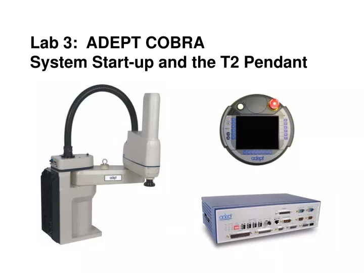
Lab 3: ADEPT COBRA System Start-up and the T2 Pendant
The COBRA Robot • Programming Modes • 1. World State (Cartesian) • Joint Mode • 3. Tool State Mode • 4. FREE Mode
Cartesian X Y Z The world coordinate system for a Cartesian robot is shown in Figure 4-5. If “X1” is selected, pressing the “+” speed bar will move the robot tool flange in the positive X direction. Pressing the “–” speed bar will move the flange in the negative X direction.
World State (Cartesian) This is a cylindrical robot that will move in Cartesian Mode. When “world” state is selected, movement in the X, Y, or Z direction is parallel to an axis of the world coordinate system. Before the speed bars will move the robot, an axis of motion must be selected from the manual control buttons. The world coordinate system for a SCARA robot is shown in Figure 4-4. If “X1” is selected, pressing the “+” speed bar will move the robot tool flange in the positive X direction. Pressing the “–” speed bar will move the flange in the negative X direction.
Joint Mode When joint state is selected, movement is about the axis of the specified joint. Figure 4-8 shows an Adept SCARA robot with three rotational joints (joints 1, 2, and 4) and one translational joint (joint 3). Positive rotation of joints 1 & 2 is counter-clockwise as viewed from above. Positive rotation of joint 4 is clockwise as viewed from above. Positive movement of joint 3 is downward. Before the speed bars will move a joint, the correct joint must be selected from the manual control buttons. Different types of motion devices will have the different joint numbers assigned to their joints. When you first move an unfamiliar robot using joint state, set the monitor speed to 10 or lower, put the robot in a safe area, and carefully move the robot using the different joint numbers to verify how the MCP moves the robot. See the documentation for the motion devices you are using for details on their joint assignments.
Tool State Mode When “tool” state is selected, movement in the X, Y, or Z direction is along an axis of the tool coordinate system. The tool coordinate system is centered at the robot tool flange with the Z axis pointing away from the flange. The positive X axis is aligned with the center of the tool flange keyway. Before the speed bars will move the robot, an axis of motion must be selected from the manual control buttons. If “X1” is selected, pressing the “+” speed bar will move the robot tool flange in the positive X direction. Pressing the “–” speed bar will move the flange in the negative X direction. In a four-axis robot, positive rotation of the gripper is clockwise as viewed from above. Figure 4-6 shows the tool state for a four-axis SCARA robot.
FREE Mode When free state is selected, individual joints are freed from servo control, and the robot brakes (if any) are released.3 Unlike the other states, you can make multiple selections from the manual control buttons to free as many joints as required. In some cases, such as joints 1 & 2 on a SCARA robot, multiple joints are freed by selecting a single button. As soon as the “COMP/PWR” button is pressed, or another selection is made from the manual control buttons, all joints are placed back under servo control and will not move freely.
FREE Mode WARNING: As soon as a joint is selected from the manual control buttons, the related joint is free to move (in some cases, multiple joints may be freed up). In many cases the weight on the joint will be sufficient to move the joint and cause damage or harm. For example, when joint 3 on a SCARA or Cartesian robot is freed, the joint is free to fall to the end of its travel. In articulated robots, multiple links of the robot may be free to fall when a single joint is freed up. Be extremely careful when selecting a joint in free mode.
The ADEPT Cobra System • Operator will use: • Front Panel • Pendant • Laptop PC
Physical Connections Before turning on the controller and enabling High Power, make sure that the following cables are installed correctly. • robot to power chassis (220 Circuit Breaker & 24VDC Breaker) • robot to controller cable • robot to Security Panel • controller to power chassis (24VDC power cable) • controller to Security Panel (Optional) • power chassis to Security Panel (Optional) • VFP to controller, Security Panel and MCP (Optional) Make sure you have installed proper safeguards and E-Stop circuits.
The Front Panel Before running programs, either the Adept Front Panel or customer-supplied switches for High Power On/Off, MAN/AUTO, and E-Stop must be connected to the SmartController XFP connector on the SmartController to enable power safely.
The Front Panel • XFP connector. Connects to the XFP connector on the SmartController. • 2. System 5V Power On LED. Indicates whether or not power is connected to the controller.
The Front Panel 3. Manual/Automatic Mode Switch. Switches between Manual and Automatic mode. In Automatic mode, executing programs control the mechanism, and the mechanism can run at full speed. In Manual mode, the system limits mechanism speed and torque so that an operator can safely work in the cell. Manual mode initiates software restrictions on robot speed, commanding no more than 250 mm/sec as required by RIA and ISO standards. Please refer to your robot manual for further details.
The Front Panel 4. High Power On/Off Switch & Lamp. Controls high power, which is the flow of current to the robot motors. Enabling high power is a two-step process. An “Enable Power” request must be sent from the user terminal, an executing program, or the MCP. Once this request has been made, the operator must press this button and high power will be applied.
The Front Panel 5. Emergency Stop Switch. The E-Stop is a dual-channel, passive E-Stop that supports Category 3 CE safety requirements. It supports a customer-programmable E-Stop delay that maintains motor power for a programmed time after the E-Stop is activated. This customizable feature allows the motors to decelerate under servo control to a stop. This can aid in eliminating coasting or overshooting on low friction mechanisms. It can also aid in the reduction of wear on highly geared, high inertia mechanisms, while maintaining safety compliance per all standards. NOTE: Instructions on configuring the E-Stop delay can be found within the SPEC.V2 section of the Instructions for Adept Utility Programs manual.
Adept COBRA Commissioning the System Turning on the robot system for the first time is known as “commissioning the system.” You must follow the steps in this section to safely bring up your robot system. The steps include: • Verifying installation, to confirm all tasks have been performed correctly. • Starting up the system by turning on power for the first time. • Verifying all E-Stops in the system function correctly. • Move each axis of the robot with the pendant to confirm it moves in the proper directions. Verifying Installation: Verifying that the system is correctly installed and that all safety equipment is working correctly is an important process. Before using the robot, make the following checks to ensure that the robot and controller have been properly installed.
Adept COBRA Commissioning the System (Continued) Mechanical Checks • Verify that the robot is mounted level and that all fasteners are properly installed and tightened. • Verify that any end-of-arm tooling is properly installed. • Verify that all other peripheral equipment is properly installed and in a state where it is safe to turn on power to the robot system. System Cable Checks: Verify the following connections: • Connect the Front Panel to the SmartController. • Connect the pendant to the SmartController, via the pendant adapter cable. • Connect user-supplied 24 VDC power to the controller. • Install a user-supplied ground wire between the SmartController and ground. • Install one end of the IEEE 1394 cable into the SmartServo port 1.1 connector on the
Adept COBRA Commissioning the System (Continued) SmartController, and install the other end into the SmartServo port 1 connector on the robot interface panel. • Install the XSYS cable between the robot interface panel XSLV safety interlock connector and XSYS connector on the SmartController, and tighten the latching screws. DANGER: After installing the robot, you must test it before you use it for the first time. Failure to do this could cause death or serious injury or equipment damage. • Connect user-supplied 24 VDC power to the robot 24VDC connector. • Connect user-supplied 200/240 VAC power to the robot 200/240VAC connector. User-Supplied Safety Equipment Checks: Verify that all user-supplied safety equipment and E-Stop circuits are installed correctly.
System Start-up Procedure Once the system installation has been verified, you are ready to start up the system. 1. Switch on the 200/240VAC power. 2. Switch on the 24VDC power to the robot. 3. Switch on the 24VDC power to the controller. 4. See Part 2 of this lab for setting up communications to the controller.) Connect to the controller via AdeptWindows PC, and boot the system from the “D” default drive. The EtherNet window should appear indicating communications from the controller to the PC. Then press OK.
System Start-up Procedure (Continued) 5. Wait for the system to complete the boot cycle. Once completed the system will return with a “dot” prompt, and the following window should be displayed.
System Start-up Procedure (Continued) 6. There should be no errors, if the boot sequence completed successfully. 7. Disengage any E-Stops. 8. If not already done so, manually move the arm away from the shipping position. Joints 1, 2, and 4 can be moved by pushing the joint. To move Joint 3, use the brake release button, located above the status panel. Make sure that you hold Joint 3, prior to pressing the brake release button. 9. Type enable power, type . ENA POW <enter> Then press the High Power button on the Front Panel while it is blinking.
System Start-up Procedure (Continued) 10. Type calibrate. CAL <enter> NOTE: The system will move slightly, with less than a 1.5 degree rotation of J4, and you might hear an audible click from the J3 brake releasing when calibration is executed. The robot is now servoing all motors to remain in position at all times. 11. System will return with a “dot” (.) prompt, if everything was successful, then high power will be enabled, and the status panel display will read “OK.” 12. System is ready for operation. 13. Type the monitor command DO READY which will cause the arm to go to a parking position which could be used for home. CAUTION, the arm will move fast, clear area first.
System Start-up Procedure (Continued) Verifying E-Stop Functions: Verify that all E-Stop devices are functional (pendant, Front Panel, and user-supplied). Test each mushroom button, safety gate, light curtain, etc., by enabling High Power and then opening the safety device. The High Power push button/light on the Front Panel should go out. Verify Robot Motions: Use the pendant to test the motion of each axis on the robot to confirm it moves in the proper directions. Refer to the Adept SmartController User’s Guide, the T1 Pendant User’s Guide or the T2 Pendant User’s Guide for complete instructions on using the pendant.
How to move the robot to coordinates in the work cell. DO NOT DROP.
Main Menu Overview The main menu is displayed when the T2 pendant is powered on. To choose one of the functions: • Press one of the function-select buttons, which are located to the left of the touchscreen. -- or – • Press one of the menu buttons, such as COMP/PWR or PROG SET.
Moving a Robot with the Pendant World State When “world” state is selected, movement in the X, Y, or Z direction is parallel to an axis of the world coordinate system. Before the speed bars will move the robot, an axis of motion must be selected from the manual control buttons. If “X1” is selected, pressing the “+” speed bar will move the robot tool flange in the positive X direction. Pressing the “–” speed bar will move the flange in the negative X direction.
Moving a Robot with the MCP Caution: If you drive a joint past its limit or for example, the Z-axis onto the table, a current sensor will sense a stalled motor and the drive power will shut down like hitting an E-Stop. An error will be indicated on the pendant with an error light. You must then enable power, clear the error, then drive the joint in the opposite direction to prevent the error from setting again. DRIVE CAREFULLY
COBRA Robot System Operation 5.1 Robot Status LED Description The robot Status LED Indicator is located on the top of the robot. The color and blinking pattern indicates the status of the robot. Figure 5-1shows the status information displayed by this LED.
COBRA Robot System Operation 5.2 Status Panel Fault Codes The status panel, shown in Figure 5-2, displays alpha-numeric codes that indicate the operating status of the robot, including detailed fault codes. Table 5-3 gives definitions of the fault codes. These codes provide details for quickly isolating problems during troubleshooting. The displayed fault code will continue to be displayed even after the fault is corrected or additional faults are recorded. All displayed faults will be cleared from the display and reset to a no-fault condition, upon successfully enabling high power to the robot, or power cycling the 24 V supply to the robot.
COBRA Robot System Operation 5.2 Status Panel Fault Codes
5.3 Using the Brake Release Button Brakes The robot has a braking system which decelerates the robot in an emergency condition, such as when the emergency stop circuit is open or a robot joint passes its soft stop. The braking system will not prevent you from moving the robot manually once the robot has stopped (and High Power has been removed). In addition, Joint 3 has an electromechanical brake. The brake is released when High Power is enabled. When High Power is turned off, the brake engages and holds the position of Joint 3. Brake Release Button Under some circumstances you may want to manually position Joint 3 on the Z-Axis without turning on High Power. For such instances, a “Z” Brake Release button is located above the robot status panel (see Figure 5-2 on page 54). When system power is on, pressing this button releases the brake, which allows movement of Joint 3. If this button is pressed while High Power is on, High Power will automatically shut down.
Lab Assignment for Lab 3Moving the Robot with the Pendant. 1. Perform the system start-up. a. Circuit Breaker on b. Front Panel system power on c. On the command line type ID to display the serial number etc. 2. Use the MCP to calibrate the robot. a. Both E-Stops pulled out b. Key switch in AUTO (or Terminal, or 100%) c. Turn on drive (enable power) by pressing COMP/PWR key 3. Select the WORLD state, using the MAN/HALT button 4. Move the Robot using the Pendant control buttons. 5. Press one of the E-Stops
Lab Assignment for Lab 3Moving the Robot with the Pendant. 6. Enable Power from the Pendant. 7. Select the JOINT state and move the various joints of the robot. 8. Select the FREE state, move each joint by hand. CAUTION: You will have to go into the workcell for this, however, your lab partner must have his hand on the E-Stop to kill it if it starts to move. 9. Actuate the gripper by pressing the T1 button or return to the monitor (COMP Button) the type DO SIG 97 to close and DO SIG -97 to open. 10. Move the robot using the Pendant control buttons and the speed bars. Pick up a part from the table left of the robot and place it on a pallet on the conveyor. • While moving display the WORLD LOCATIONS on the monitor by typing here or view on the pendant.
Lab Assignment for Lab 3Moving the Robot with the Pendant. 12. Using the slow mode and see how it can change the value of X by .01 to .02 mm. 13. Switch back from Pendant control to computer control by pressing the COMP/PWR button on the pendant. Then type DO READY to part the arm. 14. Do not turn off the power, the instructor will use the breakers to shut down. DO NOT use the switches on the controller or control panel to shut down or turn on. Use the breakers.
Lab 3: ADEPT COBRA System Start-up and the T2 Pendant Be Careful THE END