Download
1 / 34
340 likes | 356 Views
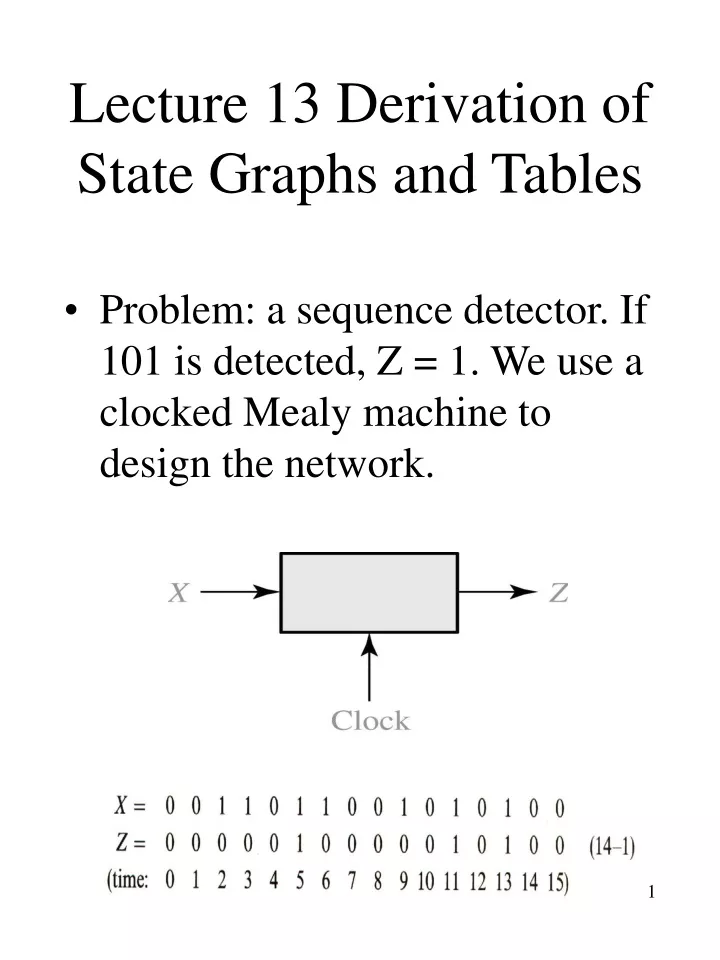
Lecture 13 Derivation of State Graphs and Tables. Problem: a sequence detector. If 101 is detected, Z = 1. We use a clocked Mealy machine to design the network. Sequence Detector. Reset state: S 0 Stay in S 0 if 0 is received, go to S 1 if 1 is received. (Remember the first 1 in S 1 )

E N D
Lecture 13 Derivation of State Graphs and Tables • Problem: a sequence detector. If 101 is detected, Z = 1. We use a clocked Mealy machine to design the network. Chap 14
Sequence Detector • Reset state: S0 • Stay in S0 if 0 is received, go to S1 if 1 is received. (Remember the first 1 in S1) • 0/0 and 1/0 (Input/Output) • In S1, if we receive a 0, then we go to another state S2 to remember that 10 has been received. • In S2, if we receive 1, then 101 is received. We must output 1. Then where should we go? Not reset (S0). But the 1 in 101 may be the first 1 of the next 101. So we go back to S1 Chap 14
Sequence Detector (cont.) • In S1, if we receive a 1, this means the restart of the 101 sequence, so we stay at S1. • In S2 (we remember 10), we also need to consider what to do if we receive a 0. This means that a 100 is received. In this case, we go back to S0 to reset. • Each state has two exit lines. Chap 14
Sequence Detector (cont.) • Convert the state graph to a state table. For the arc between S2 and S1,1/1 means that 1 output is present as soon as X becomes 1 (before the state change occurs.) Chap 14
Sequence Detector (cont.) • We need two FFs for 3 states. • We plot the next state table. Chap 14
Sequence Detector (cont.) • Suppose we use D FFs. Then the input equation of a D FF is : D = Q+ • DA = A+ = X’B • DB =B+ = X • Z = XA Chap 14
101 Detection Using a Moore Network • First reset in S0, if 1 is received, go to S1. • If a 0 is received in S1, go to S2 to remember 10. • If a 1 occurs to complete 101, we can not go back to S1 because in S1 the output is 0. We need to create another state S3. Chap 14
101 Detection (cont.) • Now we complete each state with the rest of cases that have not considered yet. Receive 10 Come to here Chap 14
101 Detection (cont.) • Find the state table from state graph. Z = AB’. AB 00 01 11 10 Chap 14
More Complex Example • Output Z = 1 if the input sequence ends in 010 or 1001. • Construct some sample input and output sequences to make sure we understand the problem statement. Chap 14
More Complex (cont.) • 010 or 1001 • First work on the sequences that lead to a 1 output. 010 first. • Start at a reset state S0 (no inputs received). • In S2, the sequence ends in 01. In S3, the sequence ends in 010. • In S3, if we receive a 1, then we are in the sequence ending in 01 . 01 is remembered in S2. So we go back to S2. Chap 14
More Complex (cont.) • Now 1001 • Start at reset state S0. If we receive 1, we go to S4 to remember that the first 1 in 1001 is received. • Then 0 is received; this means a sequence ending in 10. • Since S3 represents sequences ends in (0)10, so we go to S3 instead of creating a new state. • In S3, 0 is received. We create a new state S5 to remember 100. (but not 10) Chap 14
Complex Example (cont.) • In S5, if we received a 1, we complete the sequence 1001. Since 1001 ends in 01, we go back to S2 from S5 if 1 is received. • Patch up the rest: • In S1, 1 is already considered. 0 occurs for input (x). This is 00. No matter how many 0’s occur, the sequence ends in 0. So we stay at S1. The same as in S4. Chap 14
Complex Example (cont.) • Patch up the rest: (out-going line) • In S2, input 0 has considered. For input 1, then 11 occurs. 11 does not appear in 010 or 1001. So we don’t need another state. Since 11 ends in 1, so we go to S4. • In S5, if we get a 0 input, then the sequence ends in 000. 000 is not in 010 or 1001. 000 ends in 0. So we go back to S1. Chap 14
Moore Network Example • Problem: input X and output Z. Z = 1 if the total number of 1’s received is odd and at least two consecutive 0’s have been received. • Z only changes after the next active clock edge. (Moore machine example) Chap 14 Wait until clock edge
Moore Network Example (cont.) • Start with a reset state S0 with 0 output. • Two states to remember odd number of 1’s and even number of 1’s received respectively. • Output of S1is 0 since two consecutive 0’s have not been received. Chap 14
Moore Network Example (cont.) • In S0, if we receive a 0, then the first 0 of sequence of 00 starts. We go to S2. (S2: even 1’s and 0). • Another 0 takes us to S3 (even 1’s and 00). • In S3, if we receive 1, then 00 and odd number of 1’s occurs. We go to S4 and set output =1. Chap 14
Moore Network Example (cont.) • In S4, if we receive 1, then 00 and even number of 1’s occurs. We go back to S3. In the same way, we can construct S5 and the rest of the output going line in each state. Get 00 first then odd one Get odd one first then 00. Chap 14
Guideline for Construction of State Graph • Construct sample input and output to understand the problem. • Determine the initial state. • Construct partial graph according to the sequences that lead to a nonzero output. • Check to see if an arrow should go a new state or a previously defined state. • Check if the input sequences and output sequences match the requirement when the graph is complete. Chap 14
More example • Problem: input X and output Z. If input forms 0101 or 1001, then Z = 1. The network resets after every four inputs. Find the Mealy state graph. X = 0101 0010 1001 0100 Z = 0001 0000 0001 0000 reset reset reset Note: If 01 or 10 followed by 01, then Z = 1. Chap 14
More example (cont.) • 0101 or 1001. If 01 or 10 followed by 01, then Z = 1. • This partial graph shows 0101 and 1001 sequences. Chap 14
More example (cont.) • Wrap up the rest • Use S5 and S6 to accommodate the rest of 4-bit sequences. For S5, either 00 or 11 is received. No output of 1 is possible until the network is reset. Chap 14
Mealy Machine Example • A sequential network that generates the output sequence 0101 110110110 ….. • Homework: Realize the network. Chap 14
Moore Machine Example • Multiple inputs • Assign previous inputs to states. Chap 14
Moore Machine Example (cont.) • Derive state table • For S4, if 00 is received, the input sequence is 10,00, the output does not change. We go to S0 to remember that the last input received was 00. • If 01 is received at S4, then 10,01 is received. Then Z (= 0) is changed to 1. And we go to S3 to remember that last input was 01. Chap 14
Serial Data Code Conversion • General block diagram • Data and clock transmitted separately. • (Clock + Data) transmitted as a signal. • Need a digital phase-locked loop circuit to regenerate the clock signal at the receiver end. Chap 14
Coding Schemes • NRZ (non-return-to-zero): • Each bit is transmitted for one bit time without any change. • NRZI (non-return-to-zero Inverted-on-1s) • A 0 is encoded by no change in the transmitted value, and a 1 is encoded by inverting the previous transmitted value. (0 no change of previous value, 1 inverting previous value) Chap 14
Coding Schemes (cont.) • RZ (return-to-zero): • A 0 is transmitted as NRZ, but a 1 is transmitted as a 1 for the first half of the bit time and signal returns to 0 for the second half. • Manchester • A 0 is encoded as a 0-to-1 transition in the middle of the bit time and a 1 is encoded as a 1-to-0 transition. • Ethernet (10/100 Mbps) Chap 14
Code conversion Network (Mealy machine) • Convert a NRZ-coded bit stream to a Manchester-coded bit stream. • Clock2 is twice the frequency of the basic block. • After each conversion, reset to S0. Chap 14
Code conversion Network • State graph and table • In S1, X = 1 does not occurs because X = 00 seen from CLOCK2. • In S2, X = 0, does not occurs because X = 11. Treat them as don’t care. • Note that glitch occurs if X is delayed w.r.t. basic clock. Chap 14
Code conversion Network (Moore Machine) • Moore State graph and table • Output is delayed by one clock. (why?) • 1 input cannot occur in S1. • 0 input can not occur in S3. • Work on 00 then work on 11. Then patch up the rest. This can not be the first state for the first NRZ = 1. So either for the first 1 or 0, the output is delayed for one clock. Chap 14
State graph with variable names • In (a), all F’s (forward) for input sequence, output = Z1Z2Z3Z1Z2Z3… and all R’s for reverse output. (a) is not properly specified. • In state S0 what if F = 1 and R =1? We must resolve this by assuming F has a high priority, for instance. • In (b), R is changed to F’R. S0 to S2 if F = 0 and R = 1. Assuming input F takes priority over input R The same Chap 14
Completely specified state graph • OR all the labels emanating from a state, the result is 1. (output arcs of a state) • In S0, F + F’R + F’R’ = 1 • For every input combination, at least one next state is defined. One of the labels must be true. • AND any pair of the labels on arcs emanating from a state, the result is 0. • In S0, F. F’R = 0, F.F’R’ = 0, F’R.F’R’ = 0 • For every input combination, no more than one next state is defined. (no more than two 1’s is defined, i.e., so will not go to two states.) • If both are true, then exactly one next state is defined. Chap 14
Incompletely Specified Graph • If we know certain input combinations cannot occur, then an incompletely specified graph is acceptable! • For example, if F = 1, R must be 0 and if R = 1, F must be 0. Chap 14