Download

1 / 23
230 likes | 240 Views
Antennas. Spherical Coordinate System for Representing Antenna Patterns. Antenna Models. A Wireless InSite simulation requires both transmitters and receivers, each with an associated waveform and antenna

E N D
Spherical Coordinate System for Representing Antenna Patterns
Antenna Models • A Wireless InSite simulation requires both transmitters and receivers, each with an associated waveform and antenna • Antennas can be created from internal models or from imported data in one of several formats • The location, orientation, and polarization of the antenna will be set by the location of the associated transmitter or receiver and the rotation angles about x, y, and z axes for each association of the antenna with a transmitter or receiver
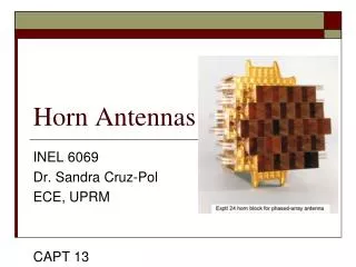
Antenna Models (2) • Built In Models • Short dipole • Linear dipole • Half-wave dipole • Ideal monopole • Linear monopole • Axial mode helix • Circular and rectangular Loops • Circular and rectangular Apertures • Circular and rectangular microstrip patch • Pyramidal horn and sectoral horns • Parabolic reflector
Antenna Models (3) Generic, Synthesized Patterns • Omnidirectional • Directional • Isotropic User Defined and Imported Patterns • XFDTD • NSMA • Planet, andothers
Antenna Models (4) Built In Antenna Models • Antenna dialog needs only a few parameters from the user and patterns are generated automatically for both propagation calculations and plotting • Approximations • References included in user’s manual • Free-standing or ground-plane mounted • Supports arrays constructed from individual elements
Antenna Models (5) • The freestanding antennas include dipoles, pyramidal horn, and parabolic reflector • For dipoles, wire is directed along z-axis • For horns and parabolic reflector antennas default orientation is along the +x-axis • Circular and square loops lie in xy plane • Axial-mode helical antenna is oriented along the x axis and radiates in the +x direction by default
Orientation and Rotation of Freestanding Antennas • Orientation and polarization is determined by adjusting the associated transmitter or receiver antenna rotations about the x, y, and z axes in the Tx/Rx properties menu • Rotations of antennas are always done in the x-y-z order for simplicity • Rotations are performed with respect to global reference frame except when Tx/Rx point is attached to a surface (points-on-face type). Rotations are then with respect to face fixed reference frame (+z is the face outward normal).
Ground-Plane Mounted Antennas • Aperture, monopole, and patch-type antennas, which are mounted on a ground plane or other planar surface, are oriented such that the antenna normal points in the +z direction by default • Antennas oriented by rotating about the z axis for a freestanding antenna or the face’s normal for a surface-mounted antenna
Isotropic pattern Omnidirectional antenna Directional antenna Circular polarization also available in addition to vertical and horizontal polarizations (along x-axis) Vertical is theta polarized outside of horizontal plane Horizontal is phi polarized Generic Antenna Patterns
User Defined and Imported Antenna Patterns • Antennas are considered to be freestanding • InSite has its own pattern data file format or can import data in several commonly used formats (NSMA, Odyssey, MSI Planet) • The pattern data used for import can be obtained from manufacturer Internet websites or generated from a full-wave electromagnetic simulator such as NEC or XFDTD.
XFDTD Format • Wireless InSite imports XFDTD far zone data exported in the user defined antenna (.uan) format or NSMA format
Adding Antennas to a Project • Right-click in Main window and select New >Antenna • Select an antenna from the database
Antenna Pattern Plotting • Right click on Antenna and select Plot Pattern • Plot shows pattern for default orientation of antenna
Choose cut-plane (mode) Constant theta or constant phi Choose spherical component Theta or phi Plot magnitude or phase Gain in dBi or normalized pattern Phase in degrees Choose frequency for built in antennas Antenna Pattern Plotting (2)
Accessed from the Antenna Properties window Combined antenna pattern Amplitude Phase Relative location Assigned to a single transmitter or receiver point Antenna Array
3-D Antenna Pattern Display • The pattern can also be viewed in the larger “selection view” window