Download
1 / 4
40 likes | 51 Views
HBD electronics discussion. Data compression how many data word is necessary per channel without loosing the crucial information. Review the old Possible new format Possible trigger outputs RPC trigger module Input to the trigger module Questions on the output. Data format.

E N D
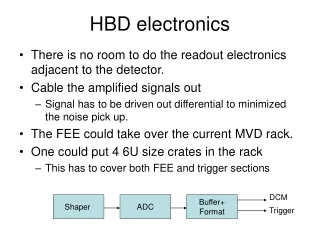
HBD electronics discussion • Data compression • how many data word is necessary per channel without loosing the crucial information. • Review the old • Possible new format • Possible trigger outputs • RPC trigger module • Input to the trigger module • Questions on the output
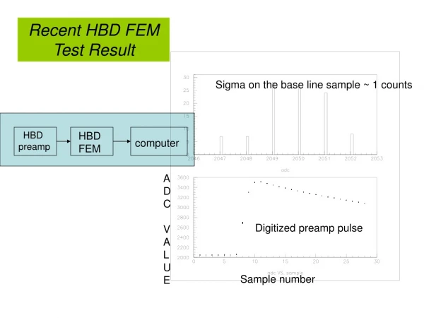
Data format • The compressed format is • one address word + 12 12-bits samples pack into 6 words. • To reduce number of data word one could keep 3 words • Pre-sample (baseline) (12 bits) • Post sample (sum over 2 or 4 samples) • Sum over 3 samples is more difficult in terms of zero suppression. • One sample in the rising edge or some location we picked • Hopefully one can pack all 3 data words + 1 address word into 2 32bits DCM word. • Once we decide this is O.K., I can discuss with engineer to see what other issues comes up… • It will takes few months for us to get new codes.
RPC trigger module • RPC TDC board has 64 channel per board • For every beam clock, we output 64 Y/N bits by 2 differential LVDS cable in the backplane. • 320 bits per cable. • We need to move 3 TDC’s data by 1 optical cable • 64*3 bits per beam clock. • The optics will run 2.8 gbits/sec. • One trigger module will handle 6 TDC modules. • 2 optical cables • The input cable can handle maximum 10 pairs cable for the L1 trigger primitives. • We could just connect all the traces to the FPGA.
HBD System Trigger • The ADC boards has 2 pairs of cables output per board, 4 LVDS signals. • It cover 48 channels • If you output 48 bits per beam clock, one bits per channel. We only need one pair cable. • The RPC trigger module could handle 10 ADC boards • The maximum data output is 384 bits. • This is less than 480 bits for 10 ADC boards. • The optics we used are the chip sets 8b/10b encoding. Except for the upgrades detector system, all other system use GLINK chip set • If HBD trigger need to merge with the existing detectors to form a trigger. We have issues with L1 system.