Download
1 / 40
460 likes | 629 Views
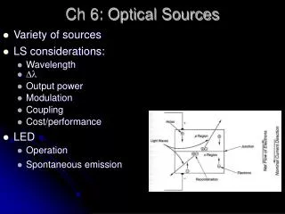
OPTICAL SOURCES LED. Requires less complex drive circuitry No thermal and optical stabilization circuits are needed Fabricated less expensively LED STRUCTURES Must have High radiance output:

E N D
OPTICAL SOURCES LED
Requires less complex drive circuitry • No thermal and optical stabilization circuits are needed • Fabricated less expensively • LED STRUCTURES • Must have • High radiance output: • Is a measure in watts, of the optical power radiated into a unit solid angle per unit area of the emitting surface. • -Response time: • Is the time delay between the application of a current pulse and the onset of optical emission. • -Quantum efficiency: • Is related to the fraction of injected electron hole pairs that recombine radiatively
To achieve high radiance and high quantum efficiency the LED structures must provide a means of confining the charge carriers and optical confinement. • Carrier Confinement: • Is used to achieve high level radiative recombination in the active region yields high quantum efficiency. • Optical Confinement: • Preventing absorption of emitted radiation by material surrounding pn junction. • To achieve carrier and optical confinement LED configurations such as homojunctions and single and double heterojunctions have been widely used. • The most effective of these structures is double heterostructure device. • Two different alloys on either side of the active region. • The band gap differences of adjacent layers confine the charge carriers. • Differences in indices of refraction of adjoining layers confine the optical field. • DIAGRAM
Other parameters influencing the device performance include • - optical absorption in the active region • Carrier recombination at the heterostructure interfaces • Doping concentration of the active layer • Injection carrier density • Active layer thickness • Two basic LED configurations being used for fiberoptics are • -Surface Emitters • - The plane of the active light emitting region is oriented perpendicularly to the axis of the fiber. • - A well is etched through the substrate of the device, into which a fiber is cemented in order to accept the emitted light. • - The emission pattern is isotropic with 120deg half power beam width. • - This pattern from a surface emitter is called Lambertian pattern. • - In this the source is equally bright when viewed from any direction, but the power diminishes as cos theta . • DIAGRAM
Edge Emitter • - Consists of an active junction region and two guiding layers. • - This forms the waveguide channel that directs the optical radiation toward the fiber core. • - Emission pattern is more directional than surface emitter. • - Plane parallel to the junction – half power width of theta=120deg • - plane perpendicular to the junction- half power width of theta=25-35deg • DIAGRAM • LIGHT SOURCE MATERIALS • The active layer of an optical source must have direct band gap. • DB produce adequate level of optical emission, group III-V materials are DB material. • For the operation in the 800-900nm, the principle material used is Ga1-xAlxAs • The ratio x of aluminium arsenide to gallium arsenide determines the band gap of the alloy and the wavelength of the peak emitted radiation. • The value of x for the active area material is usually chosen to give emission wavelength of 800-850nm.
An example of Ga1-xAlxAs LED with x=0.08 peak output occurs at 810nm. • The width of the spectral pattern at its half power point is known as Full Width Half Maximum(FWHM) spectral width, is 36nm. (GRAPH) • A very close match between the crystal lattice parameters is required to reduce • - interfacial defects • - minimize strain in the devices as the temp varies • Fundamental quantum mechanical relationship • E=hע=hc/λ • Peak emission wavelength in micrometers can be expressed as a function of the band gap energy Eg by the equation • λ=1.240/Eg • - A heterojunction with matching lattice parameters is created by choosing two material compositions that have the same lattice constant but difference band gap energies.
QUANTUM EFFICIENCY AND LED POWER • The excess densities of electrons n and holes p are equal, since the injected carriers are formed and recombine in pairs with the reqiurement of charge neutrality in the crystal. • When carrier injection stops the carrier density returns to the equilibrium value. • The excess carrier density decays exponentially with time according to the relation n=noe-t/ז • no= initial injected excess electron density • ז= carrier life time depends on material composition and device defects • The excess carrier can recombine either radiatively and non-radiatively • When there is a constant current flow into an LED a equilibrium condition is established. • The total rate at which carriers are generated is the sum of externally supplied and thermally generated rates. • Derivation
Not all internally generated photons will exit the device. • To find the emitted power, need to consider external quantum efficiency. • Defined as the ratio of the photons emitted from the LED to the number of internally generated photons. • To find external quantum efficiency , reflection effects at the surface of the LED have to be taken into account. • EXPRESSION&DIAGRAM • MODULATION OF A LED: • The frequency response of an LED is largely determined by 3 factors: • Doping level in the active region • Injected carrier lifetime • Parasitic capacitance of LED • - The modulation bandwidth of an LED can be defined in either electrical or optical terms.
Modulation bandwidth is defined as the point where the electrical signal power, designated by p(w) has dropped to half its constant value resulting from the modulated portion of the optical signal. • This is the electrical 3dB point that is the freq at which the output electrical power is reduced by 3dB wrt input electrical power. • p(w)=I2(w)/R • Ratioelec=10log[p(w)/p(o)]=10log[I2(w)/I2(o)] • I(w)= electric current in the detection circuitry • The electrical 3dB point occurs at that freq point where the detected electrical power p(w)=p(o)/2 • I2(w)/I2(o)=1/2 • I(w)/I(o)=0.707 • The modulation bandwidth of an LED is given in terms of 3dB bandwidth of the modulated optical power P(w), it is specified at the frequency where P(w)=Po/2 • In this case the 3dB bandwidth is determined from the ratio of the optical power wrt freq w to the unmodulated value of the optical power. • Ratiooptical=10log[P(w)/P(o)]=10log[I(w)/I(o)]=0.500 • GRAPH
Laser come in many forms • The lasing medium can be gas, a liquid, an insulating crystal or a semiconductor. • For optical fiber systems the laser sources used are semiconductor laser diodes. • Spatial and temporal coherence, highly monochromatic ,very directional. • Laser action is the result of 3 key processes: • -photon absorption • - spontaneous emission • - stimulated emission
In thermal equilibrium the density of excited electrons is very small. • Stimulated emission will exceed absorption only if the population of the excited states is greater than that of ground state. This condition is known as Population Inversion. • Population Inversion is achieved by various pumping techniques. • Laser Diode Modes and Threshold Conditions • Virtually all laser diodes in use are multilayered heterojunction devices. • Stimulated emission in semiconductor lasers arises from optical transitions between distributions of energy states in the valence and conduction bands. • This differs from gas and solid state lasers, in which radiative transitions occur between discrete isolated atomic and molecular levels. • The radiation in the laser diode is generated within a Fabry-Perot resonator cavity. • A pair of flat , partially reflected mirrors are directed toward each other to enclose the cavity. • The purpose of these mirrors is to provide strong optical feedback, thereby converting a device into an oscillator with a gain mechanism that compensates for optical losses in the cavity.
The laser cavity can have many resonant frequencies. • The device will oscillate for those resonant frequencies. • The sides of the cavity are formed by roughening the edges of the device to reduce unwanted emission in these directions.
Distributed Feedback laser: • Cleaved facets are not required for optical feedback. • Lasing action is obtained from Bragg reflectors or periodic variations of the refractive index which are incorporated into the multilayer structure along the length of the diode.
-The optical radiation within the resonance cavity of a laser diode sets up a pattern of electric and magnetic field lines called modes of the cavity. • These can be separated into two independent sets of transverse electric and transverse magnetic modes. • Each set of modes can be described in terms of lateral, longitudinal and transverse variations of the electromagnetic fields. • The longitudinal modes are related to the length of the cavity, and determine the principle structure of the frequency spectrum of the emitted optical radiation. • Lateral modes lie on the plane of the pn junction. These mode depend on the side wall preparation and the width of the cavity and determine the shape of the lateral profile of the laser beam. • Transverse modes are associated with the electromagnetic field and the beam profile in the direction perpendicular to the plane of the pn junction. • To determine lasing conditions and the resonant frequencies, the electromagnetic wave propagating in the longitudinal direction in terms of electric field phasor is given by • EQUATIONS
Laser Diode Rate Equations: • The relation between the optical power output and diode drive current can be determined by examining the rate equations. • The total carrier population is determined by carrier injection, spontaneous recombination and stimulated emission. • For a pn junction with a carrier confinement region of depth d, the rate equations are given by • and • C- is the coefficient describing the strength of the optical absorption and emission interactions
Decay in the photons caused by loss mechanisms No of photons produced by spontaneous emission Source of photons resulting from stimulated emission No. of the electrons lost from the conduction band owing to spontaneous and stimulated emissions Increase in the electron conctn in the conduction band as current flows into the device - Solving these two equations will yield expression for output power.
External Quantum Efficiency: • Is defined as number of photons emitted per radiative electron hole pair recombination above threshold • Experimentally it is calculated from • Eg = bandgap energy in electron volts • dP = incremental change in emitted output power • dI = Incremental change in drive current • λ=emission wavelength
LASER DIODE STRUCTURES AND RADIATION PATTERNS • Basic requirement for efficient operation of laser diodes, the current flow must be restricted laterally to a narrow stripe along the length of the laser. • Three basic optical confinement methods used for bounding laser light in the lateral direction. • Gain guided laser • Positive index waveguide • Negative index waveguide
LIGHT SOURCE LINEARITY • - In analog applications any device nonlinearities will create frequency components in the output signal that were not present in the input signal. • Two important nonlinear effects are harmonic and intermodulation distortions. • Harmonic distortion – • - Non-linearities are the result of inhomogeneities in the active region of the device and arise from power switching between the lateral modes in the laser. These are referred to as ‘kinks’ .
MODAL,PARTITION AND REFLECTION NOISE • Modal or speckle noise: (speckle pattern – mutual interference of set of wavefronts) • -Noise is generated when speckle pattern changes in time. • The continuously varying speckle pattern that falls on the photodetector produces a time varying noise in the received signal. • Mode partition Noise: • - Is associated with intensity fluctuations.
Reflection Noise: • Is associated with linearity distortion caused by some of the light output being reflected back into the laser cavity from fiber joints. • The reflected power couples with the lasing modes thereby causing their phases to vary.
RELIABILITY CONSIDERATIONS: • Degradation of light sources can be divided into three basic categories. • Internal damage: • This effect arises from the migration of crystal defects into the active region of the light source. These defect decrease the internal quantum efficiency. • Ohmic contact deterioration: • This effect is a function of the solder used to bond the chip to the heat sink, the current density through the contact and the contact temperature. • Facet damage: • - This degradation reduces the laser mirror reflectivity and increases the nonradiative carrier recombination at the laser facets.
PHOTODETECTORS • Receiving device • Converts variation of optical power into correspondingly varying electric current • Should be insensitive to variations in temperature • Different types of photodetectors are in existence: • - photomultipliers • - pyroelectric detectors • - semiconductor based photodiodes • Semiconductor photodiodes is used exclusively because of its small size,high sensitivity and fast response time. • Two types of photodiodes : pin photodiode and avalanche photodiode
The pin Photodetector: • The device structure consists of p and n regions separated by very lightly n-doped intrinsic(i) region. • Large reverse bias voltage is applied , intrinsic region is fully depleted of carriers. • When photon is incident , can give up its energy and excite an electron from valence band to the conduction band. This process is known as Photocarriers. • The high electric field present in the depletion region causes the carriers to separate. • This gives rise to a current flow in the external circuit, with one electron flowing for every carrier pair generated. • This current flow is known as photocurrent.
As the charge carriers flow through the material , some electron –hole pairs will recombine and disappear. • The charge carriers move a distance, this distance is known as diffusion length. • The time it takes for an electron or hole to recombine is known as carrier life time. • The life time and diffusion length is related by the expressions • Ln=(Dnזn)1/2 and Lp=(Dpזp)1/2 • Optical radiation is absorbed in the semiconductor material according to the exponential law • P(x)= P0(1-e-αs(λ)x) • αs(λ)= absorption coefficient at a wavelength λ • P0= incident optical power level • P(x)=optical power absorbed in a distance x • - A particular semiconductor material can be used only over a limited wavelength range.
The upper wavelength cutoff λc is determined by the band gap energy of the material. • λc= hc / Eg = 1.24/Eg(ev) • The photoresponse cuts off as a result of very large values of αs at the shorter wavelengths. • In this case photons are absorbed very close to the photodetector surface where the recombination time of the generated electron hole pairs is very short. • The generated carriers thus recombine before they can be collected by the photodetector circuitry.
Taking into account the reflectivity at the entrance of the photodiode then the primary current resulting from the power absorption is given by • Two important characteristics of a photodetector are quantum efficiency and response speed. • These parameters depend on material band gap, operating wavelength, and the doping and thickness of p,i and n regions of the device. • The quantum efficiency η is the number of electron hole carrier pairs generated per incident photon energy hע and is given by • η= Ip/q / Po/h ע • To achieve a high quantum efficiency , the depletion layer must be thick to permit large fraction of the incident light to be absorbed. • The thicker the depletion layer the longer it takes for the photogenerated carriers to drift across the reverse biased junction.
The performance of photodiode is characterized by Responsivity R. This is related to quantum efficiency by • R= Ip/Po = ηq/hע • In most photodiodes the quantum efficiency is independent of the power level falling on the detector. • Responsivity is a linear function of the optical power. • The responsivity is a function of wavelength and of the photodiode material. • Avalanche photodiode • Internally multiply the primary signal photocurrent • In order of carrier multiplication , the photogenerated carriers must traverse a region where a very high electric field is present. • In this high field region a photogenerated electron or hole can gain enough energy so that it ionizes bound electrons in the valence band upon colliding them. • This carrier multiplication mechanism is known as impact ionization. • The newly created carriers are also accelerated by high electric field to cause further impact ionization. This phenomenon is the avalanche effect.
- A commonly used structure for achieving this carrier multiplication is the reach through construction. • This configuration is referred to as p+πpn+reach through structure. • The average number of electron hole pairs created by a carrier per unit distance travelled is called the ionization rate. • The multiplication M for all carriers generated in the photodiode is defined by M=IM/Ip • IM= average value of total multiplied output current Ip=primary unmultiplied output current
pin photodiode avalanche photodiode
Detector Response Time Depletion Layer photocurrent: Schematic representation of a reverse – biased pin photodiode:
The principle noises associated with the photodetectors are • Quantum noise • Dark current noise generated in the bulk material of the photodiode • Surface leakage current noise • Quantum Noise: • Arises from the statistical nature of the production and collection of photoelectrons when a optical signal is incident on a photodetector. • Bulk dark current: • Arises from the electrons and or holes which are thermally generated in the pn junction of the photodiode. • Surface leakage current: • Simply the leakage current , dependent on surface defects, cleanliness, bias voltage and surface area.
Effective way of reducing surface dark current is through the use of a guard ring structure which shunts leakage current away from the load resistor. • RESPONSE TIME • The response time of photodiode depends mainly on 3 factors: • The photodiode parameters responsible for these factors are: • Absorption coefficient • The depletion region width • Photodiode junction • Package capacitances, amplifier capacitances • Detector load resistance, amplifier input resistance, and photodiode series resistance
The transit time of the photocarriers: • Depends on carrier drift velocity and depletion layer width • The diffusion process are compared with the drift of carriers in the high field region. • The response time is described by the rise and fall time of the detector output. partially depleted region Fully depleted region
Devices with very thin depletion regions tend to show slow and fast response components. • The fast component in the rise time is due to carriers generated in the depletion region. • Slow component arises from the diffusion of carriers that are created from the edge of the depletion region. • The junction capacitance is