Download
1 / 54
620 likes | 1.53k Views
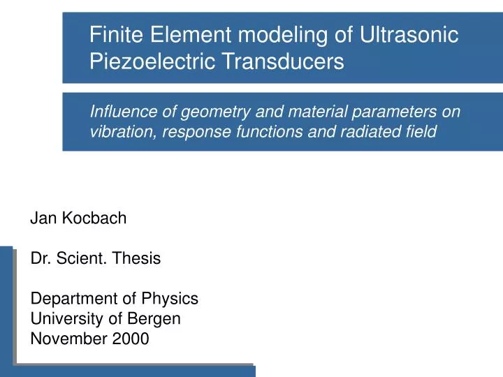
Finite Element modeling of Ultrasonic Piezoelectric Transducers. Influence of geometry and material parameters on vibration, response functions and radiated field. Outline. Motivation Piezoelectric materials Piezoelectric transducers FE modeling of transducers and surrounding fluid

E N D
Finite Element modeling of Ultrasonic Piezoelectric Transducers Influence of geometry and material parameters on vibration, response functions and radiated field
Outline • Motivation • Piezoelectric materials • Piezoelectric transducers • FE modeling of transducers and surrounding fluid • Results: • Systematic analysis for piezoelectric disks • Systematic analysis for piezoelectric disks with a front layer • Conclusions - noe om objectives med arbeidet må sies tidlig! NB! Fokuser mere på hva som er nytt i dette arbeidet, istedenfor å vise masse forskjellige enkeltting. Se på konklusjoner, objectives osv. for å se hva det er som er nytt!! - Egenmoder: Nytt at ny mode klassifiserings system. Resp.fu: Nytt at systematisk vist. - Frontlag: Mye nytt og spennende
Choose a basic design based on needs and experience Vary design parameters in simulation tool until desired properties Repeat until prototype has desired properties Build a prototype (expensive!) Accurate simulation tool few repetitions required A typical example of a combined numerical/experimental trnasducer design process. Motivation • Increased understanding and control in a transducer design process Without appropriate simulation tools, all of the variation of design parameters must be made using measurements only. This is a time-consuming and expensive process. Candidate
Voltage applied mechanical distortion surface electrode piezoelectric bar • AC field alternate in size sound radiated Piezoelectric materials • Piezoelectric effect: • Mechanical stress applied voltage produced New figure here?
Piezoelectric materials • Equations governing a piezoelectric material: Sjekk disse ligningene p[ tensor form!!!
Piezoelectric transducers • Found in a wide range of different applications • e.g. medical ultrasound, ultrasonic measurement systems, sonars, ultrasonic distance measurement, non-destructive testing, process instrumentation ..... Need som more here. Fra sluttrapport! • Many different types of transducer structures • e.g. disk transducers, bar transducers, ring transducers, transducer arrays, unimorph/bimorph transducers ..... • Present work restricted to axisymmetric piezoelectric disk transducers Need som more here
Frontlayer Piezoelectric disk Backing layer The central part of a piezoelectric disk transducer is the piezoelectric disk. There is a large impedance mismatch between typical piezoelectric materials applied in a piezoelectric disk transducer and air or water, and therefore a front layer is applied for better matching between the piezoelectric disk and the fluid medium. A backing layer is applied at the back of the disk to damp down vibrations. A transducer housing is also often applied, to protect the transducer from the operating environment. Piezoelectric transducers • Axisymmetric piezoelectric disk transducers + Fluid medium + Transducer housing
The central part of a piezoelectric disk transducer is the piezoelectric disk. There is a large impedance mismatch between typical piezoelectric materials applied in a piezoelectric disk transducer and air or water, and therefore a front layer is applied for better matching between the piezoelectric disk and the fluid medium. A backing layer is applied at the back of the disk to damp down vibrations. A transducer housing is also often applied, to protect the transducer from the operating environment. Piezoelectric transducers • Axisymmetric piezoelectric disk transducers + Fluid medium Frontlayer Piezoelectric disk Present work: Focus on the basic parts of the transducer: disk + frontlayer + fluid medium Backing layer + Transducer housing
Transducer vibration • Transducer response functions- Impedance/Admittance - Source sensitivity response • Radiated sound field- Directivity pattern - Near and farfield pressure field Piezoelectric transducers • Transducer properties studied: Nevne andre ”transducer properties”,som for eksempel mottakerfølsomhet o.l.
Transducer modeling • Possible approaches: • Use commercial simulation tool • Develop new simulation tool • New simulation tool developed: FEMP • Why develop new? • Research tool: • Implement/evaluate different methods and identify best approach • Systematic analysis • Commercial tools difficult to tailor for efficient systematic analyses • 3D approach required for accurate modeling
FEMP: Modeling approach \posding No need to mesh fluid region & \negding Part of fluid region must be meshed \posding Small BE matrices & \negding Large FE matrices \negding BE matrices are full & \posding FE matrices are sparse \negding Problems at characteristic frequencies & \posding No problems at any frequencies \negding Evaluation of singular integrals& \posding All integrals may be evaluated easily \negding Computationally intensive to calculate field & \posding Field is calculated automatically \negding BE matrices must be set up for every frequeny & \posding FE matrices set up only once Astley-Leis inf. el: Applied in near field. Field easily calculated in far field. Say something about which properties are important for the method implemented here! • Desired properties of simulation tool • Model complete axisymmetric piezoelectric transducer + fluid medium • Efficient calculation of vibration, response functions and sound field • Efficient calculation in a large frequency band • Modeling approach for piezoelectric medium: • Finite element method / Finite difference method / Boundary element method • Modeling approach for infinite fluid medium : • Fluid finite elements + infinite elements / Fluid boundary elements / Fluid finite elements + dampers / Fluid finite elements + analytical solution / etc. • conjugated Astley-Leis inf. el. / unconjugated Astley-Leis inf. el. / conjugated or unconjugated Burnett inf. el. / Olson-Bathe inf. el. / etc. • Harmonic analysis method : • Mode superposition method / Direct harmonic solution / FFT from time domain • Loss model for piezoelectric medium : • Complex material constants / Structural friction force / Rayleigh damping • Different modeling approaches evaluated to find best approach Si en del om de forskjellige metodene, ulemper/fordeler osv. her!
FEMP: Theory • FE formulation set up using Galerkin method • Set up weak formulation variational formulation • Divide region of analysis into elements and nodes • Set up FE equations from variational formulation
( ) (piezoelectric) (piezoelectric) ( ) (fluid) FEMP: Theory • Set up weak formulation • apply boundary conditions • results in variational formulation
Piezoelectric finite elements Fluid finite elements Fluid infinite elements FEMP: Theory • Divide region of analysis into elements and nodes
û3 û7 û4 û8 û6 û1 û5 û2 Interpolation functions (quadratic + variable order) FEMP: Theory • Divide region of analysis into elements and nodes • Unknowns approximated by nodal values in each element using interpolation functions
Calculation of one matrix as example?? Size of system? Boundary conditions? FEMP: Theory When the region of analysis is divided into nodesand elements, a set of matrix equations, also called theFE equations, may be set up. • Set up FE equations : set of matrix equations • FE matrices calculated for each local element • Assembled to global FE matrices • Solved for unknown quantities for each frequency
Input conductance [S] f [kHz] FEMP: Verification • Comparison with other FE codes • ABAQUS, ANSYS, CAPA: < 5 ppm difference (resonance freq.) • Comparison with measurements • good qualitative agreement (resonance freq., response funct.) Input conductance of PZT-5A disk with D/T=12 in water.
normalized pressure p normalized distance S FEMP: Verification • Comparison with other FE codes • ABAQUS, ANSYS, CAPA: < 5 ppm difference (resonance freq.) • Comparison with measurements • good qualitative agreement (resonance freq., response funct.) • Comparison with analytical solution • good quantitative agreement (plane piston pressure field) On-axis pressure field from plane-piston radiator
FEMP: Verification • Comparison with other FE codes • ABAQUS, ANSYS, CAPA: < 5 ppm difference (resonance freq.) • Comparison with measurements • good qualitative agreement (resonance freq., response funct.) • Comparison with analytical solution • good quantitative agreement (plane piston pressure field) • Comparison with literature results • good qualitative agreement (resonance freq., response funct.)
Frontlayer Tfront Piezoelectric disk T • D/T ratio of disk • Thickness of front layer D • Disk material • Frontlayer material Fluid medium • Fluid medium (air/water) Analysis results • Focus of investigations: • How does systematic variation of geometry and material parameters influence on transducer properties? • Present analysis made for piezoelectric disks and piezoelectric disks with a front layer Dette kan evt. gjøres annerledes ved at man viser hvordan design parametrene endres grafisk, kutter ut menypunkter på at man kun ser på disk+frontlag (sagt før).
Challenges related to analysis Komme med konklusjonene av analysen her, og så trekke ut eksempler etterpå! NB! Ta med konkl. av FE program o.l. tidligere et sted, eventuelt skrive det inn her! • All of the analysis: • Quantify the accuracy in the results • Piezoelectric disks: • refine previous mode classification scheme • relation vibrational modes peaks in response functions • relation disk vibration radiated sound field • Piezoelectric disks with a front layer: • analysis for thick disks • analysis for radial mode transducers • differences in optimal front layer thickness and materials • how to change geometry and material parameters to avoid unwanted peaks and dips in response functions Forklare bakgrunnen for valg av kvartbølgelag, og hva som forventes av et kvartbølgelag, hva de 1D modellene sier, og at det stort sett har blitt brukt 1D modeller i bestemmelse av optimal frontlags tykkelse og materialvalg.
Accuracy considerations • Literature: no clear answer for piezoelectric media • 2 -10 elements per needed for “sufficient accuracy” • What is “sufficient accuracy”? • Application dependent • 5-10% error tolerated in some applications • Resonance freq. (e.g. for material constant evaluation):ppm level • Challenge: • How many elements to get a specified accuracy? • Answer through convergence tests • Accuracy found as function of elements per wavelength
5 elements per wavelength max 0.25% error 10 elements per wavelength max 100 ppm error Accuracy considerations • Example: Convergence test for resonance freq.(quadratic elements) • Corresponding convergence tests made for response functions and radiated field
Analysis results: Piezoelectric disks Komme med konklusjonene av analysen her, og så trekke ut eksempler etterpå! NB! Ta med konkl. av FE program o.l. tidligere et sted, eventuelt skrive det inn her! • Mode classification scheme • Relation between eigenmodes and radiated field • Relation between eigenmodes and response functions Forklare bakgrunnen for valg av kvartbølgelag, og hva som forventes av et kvartbølgelag, hva de 1D modellene sier, og at det stort sett har blitt brukt 1D modeller i bestemmelse av optimal frontlags tykkelse og materialvalg.
The refined mode classification schemedeveloped in the present work is a basis for the remainderof the work. Piezoelectric disks: mode classification • Mode classification scheme developed based on: • resonance frequency spectra • vibration of disks for varying geometry and materials • Vibrational modes classified into • R modes • E modes • A modes • L modes • Thickness extensional modes and thickness shear modes special types of A and L modes
Thick disks: D/T=1 frequency-thickness product [kHz mm] Thin disks: D/T=20 Diameter/Thickness ratio The refined mode classification schemedeveloped in the present work is a basis for the remainderof the work. Piezoelectric disks: mode classification Example: PZT-5A disks • Resonance frequency spectrum of PZT-5A disks • Resonance frequencies of disks shown as a function of D/T ratio
Piezoelectric disks: R modes Mode classification difficultdue to strong mode couplingto E, A and L modes frequency-thickness product [kHz mm] R modes, associated with 1st order symmetric Lamb wave in infinite plate Diameter/Thickness ratio
R1: D/T=5 R1: D/T=10 R1: D/T=20 Piezoelectric disks: R modes Fundamental radial mode:Disk expands in thicknessdirection when it contracts inradial direction. frequency-thickness product [kHz mm] Diameter/Thickness ratio
R4: D/T=10 R3: D/T=10 R2: D/T=10 Piezoelectric disks: R modes frequency-thickness product [kHz mm] Higher order radial modes:number of nodal circles with zeroradial displacement increases withorder of radial modes. Diameter/Thickness ratio
Piezoelectric disks: R modes frequency-thickness product [kHz mm] R1: D/T=5 (water) Diameter/Thickness ratio
E mode: D/T=10 E mode: D/T=5 Piezoelectric disks: E mode frequency-thickness product [kHz mm] E mode Large axial displacement at circular edge of disk. Diameter/Thickness ratio
Piezoelectric disks: E mode E-mode: D/T=5 (water) frequency-thickness product [kHz mm] Diameter/Thickness ratio
A2 mode: D/T=10 A1 (TS1) mode: D/T=8 A1 (TS1) mode: D/T=5 Piezoelectric disks: A modes New numbering scheme for A modes suggested A4 A7 A2 A3 A5 A6 A1 frequency-thickness product [kHz mm] A modes, associated with 2nd order symmetric Lambmode in infinite plate PZT-5A: A1 = TS1 Diameter/Thickness ratio
L2 mode: D/T=10 L1(TE1) mode: D/T=14 L1(TE1) mode: D/T=10 Piezoelectric disks: L modes frequency-thickness product [kHz mm] ideal: no R mode coupling L modes, associated with 3rd order symmetric Lambmode in infinite plate PZT-5A: L1 = TE1 Diameter/Thickness ratio
Piezoelectric disks: L modes L1 (TE1) modeD/T=5 (water) frequency-thickness product [kHz mm] Diameter/Thickness ratio
Piezoelectric disks: response functions • Relation between peaks in response functions and eigenmodes: • Found by comparing resonance frequency spectrum and response functions • Example for electrical input conductance of PZT-5A disk with D/T=10
L2 R12 L1(TE1) A4 R9 A3 A2 A1 R8 R7 R6 E R5 frequency-thickness product [kHz mm] frequency-thickness product [kHz mm] R4 R3 R2 R1 Diameter/Thickness ratio Conductance [mS] Piezoelectric disks: response functions • Relation: Resonance frequency spectrum response functions
Analysis results: Piezoelectric disk with a frontlayer Komme med konklusjonene av analysen her, og så trekke ut eksempler etterpå! NB! Ta med konkl. av FE program o.l. tidligere et sted, eventuelt skrive det inn her! • Why to use a frontlayer - general theory • 1D model results valid for thin disks • 3D model results for thick disks • 3D model results for radial mode transducers Forklare bakgrunnen for valg av kvartbølgelag, og hva som forventes av et kvartbølgelag, hva de 1D modellene sier, og at det stort sett har blitt brukt 1D modeller i bestemmelse av optimal frontlags tykkelse og materialvalg.
Fluid medium: Z 400 rayl -1.5 Mrayl Piezoelectric disk: Z 35 Mrayl T D Først disk+medium. Vise impedans. Stor impedansforskjell -> lite energi gjennom (skrive eksplisitt?). Så sette frontlag imellom, og illustrere at mer energi kommer gjennom pga. transformator. Hvordan illustrere? Grafisk illustrasjon på dette? Skiven ”ser” større strålingsimpedans! Piezoelectric disks with a front layer:General theory • Piezoelectric disk in water/air/gas: quarterwave transformator? -> of intermediate acoustic impedance • large acoustic impedance mismatch: • low bandwidth • low acoustic transmission coefficient
Frontlayer: Z = ??? Tfront Først disk+medium. Vise impedans. Stor impedansforskjell -> lite energi gjennom (skrive eksplisitt?). Så sette frontlag imellom, og illustrere at mer energi kommer gjennom pga. transformator. Hvordan illustrere? Grafisk illustrasjon på dette? Skiven ”ser” større strålingsimpedans! Piezoelectric disks with a front layer:General theory • Piezoelectric disk in water/air/gas: Fluid medium: Z 400 rayl -1.5 Mrayl Solution: matching layer for better transmission quarterwave transformator? -> of intermediate acoustic impedance Piezoelectric disk: Z 35 Mrayl T D Important parameters for bandwidth and transmission • large acoustic impedance mismatch: • low bandwidth • low acoustic transmission coefficient
Først disk+medium. Vise impedans. Stor impedansforskjell -> lite energi gjennom (skrive eksplisitt?). Så sette frontlag imellom, og illustrere at mer energi kommer gjennom pga. transformator. Hvordan illustrere? Grafisk illustrasjon på dette? Skiven ”ser” større strålingsimpedans! Piezoelectric disks with a front layer:Example • Most previous work: 1D, thin disks/plates, TE1 mode • Quarterwave thick frontlayer for optimal transmission • Optimal acoustic impedance of front layer given by: • Zfront = (Zpiezo Zfluid)1/2 • Zfront =2 1/3 (Zpiezo )1/3(Zfluid)2/3 • Zfront = (Zpiezo )1/3(Zfluid)2/3 • Other transducer configurations and modes: • Other optimal values for frontlayer thickness and acoustic impedance quarterwave transformator? -> of intermediate acoustic impedance • Example: • PZT-5A (D/T=5) with epoxy frontlayer (Zfront=4.17 Mrayl ) in water • Comparison 1D model and 3D model for TE1 mode region
Først disk+medium. Vise impedans. Stor impedansforskjell -> lite energi gjennom (skrive eksplisitt?). Så sette frontlag imellom, og illustrere at mer energi kommer gjennom pga. transformator. Hvordan illustrere? Grafisk illustrasjon på dette? Skiven ”ser” større strålingsimpedans! Piezoelectric disks with a front layer:Thick disk, TE1 mode region • Without frontlayer: One narrow peak • Two peaks in response functions with positions varying with Tfront. Without frontlayer quarterwave transformator? -> of intermediate acoustic impedance 1D modelresult conductance [dB re 1 mS] normalized frequency f/fTE1 conductance [dB re 1 mS] normalized frontlayer thickness Tfront /T/4,TE1 normalized frequency f/fTE1
Først disk+medium. Vise impedans. Stor impedansforskjell -> lite energi gjennom (skrive eksplisitt?). Så sette frontlag imellom, og illustrere at mer energi kommer gjennom pga. transformator. Hvordan illustrere? Grafisk illustrasjon på dette? Skiven ”ser” større strålingsimpedans! Piezoelectric disks with a front layer: Thick disk, TE1 mode region • Equal height at quarterwave thickness • Low Zfront one wide peak at quarterwave thickness Tfront = 1.0 T/4,TE1 Zfront = 4.17 Mrayl quarterwave transformator? -> of intermediate acoustic impedance conductance [dB re 1 mS] normalized frequency f/fTE1 conductance [dB re 1 mS] normalized frontlayer thickness Tfront /T/4,TE1 normalized frequency f/fTE1
Først disk+medium. Vise impedans. Stor impedansforskjell -> lite energi gjennom (skrive eksplisitt?). Så sette frontlag imellom, og illustrere at mer energi kommer gjennom pga. transformator. Hvordan illustrere? Grafisk illustrasjon på dette? Skiven ”ser” større strålingsimpedans! Piezoelectric disks with a front layer: Thick disk, TE1 mode region Without front layer quarterwave transformator? -> of intermediate acoustic impedance TE1 A2 A1 conductance [dB re 1 mS] normalized frequency f/fTE1 conductance [dB re 1 mS] normalized frontlayer thickness Tfront /T/4,TE1 normalized frequency f/fTE1
Først disk+medium. Vise impedans. Stor impedansforskjell -> lite energi gjennom (skrive eksplisitt?). Så sette frontlag imellom, og illustrere at mer energi kommer gjennom pga. transformator. Hvordan illustrere? Grafisk illustrasjon på dette? Skiven ”ser” større strålingsimpedans! Piezoelectric disks with a front layer: Thick disk, TE1 mode region Tfront = 0.6 T/4,TE1 Zfront = 4.17 Mrayl quarterwave transformator? -> of intermediate acoustic impedance A2 TE1 conductance [dB re 1 mS] A1 normalized frequency f/fTE1 conductance [dB re 1 mS] normalized frontlayer thickness Tfront /T/4,TE1 normalized frequency f/fTE1
Først disk+medium. Vise impedans. Stor impedansforskjell -> lite energi gjennom (skrive eksplisitt?). Så sette frontlag imellom, og illustrere at mer energi kommer gjennom pga. transformator. Hvordan illustrere? Grafisk illustrasjon på dette? Skiven ”ser” større strålingsimpedans! Piezoelectric disks with a front layer: Thick disk, TE1 mode region Tfront = 0.8 T/4,TE1 Zfront = 4.17 Mrayl quarterwave transformator? -> of intermediate acoustic impedance A2 TE1 conductance [dB re 1 mS] A1 normalized frequency f/fTE1 conductance [dB re 1 mS] normalized frontlayer thickness Tfront /T/4,TE1 normalized frequency f/fTE1
Først disk+medium. Vise impedans. Stor impedansforskjell -> lite energi gjennom (skrive eksplisitt?). Så sette frontlag imellom, og illustrere at mer energi kommer gjennom pga. transformator. Hvordan illustrere? Grafisk illustrasjon på dette? Skiven ”ser” større strålingsimpedans! Piezoelectric disks with a front layer: Thick disk, TE1 mode region Tfront = 1.0 T/4,TE1 Zfront = 4.17 Mrayl quarterwave transformator? -> of intermediate acoustic impedance A2 conductance [dB re 1 mS] normalized frequency f/fTE1 conductance [dB re 1 mS] problem normalized frontlayer thickness Tfront /T/4,TE1 normalized frequency f/fTE1
Først disk+medium. Vise impedans. Stor impedansforskjell -> lite energi gjennom (skrive eksplisitt?). Så sette frontlag imellom, og illustrere at mer energi kommer gjennom pga. transformator. Hvordan illustrere? Grafisk illustrasjon på dette? Skiven ”ser” større strålingsimpedans! Piezoelectric disks with a front layer: Thick disk, TE1 mode region • Corresponding systematic analysis made for the source sensitivity response (acoustic response): • Several different front layer materials • Avoid dips in otherwise flat response by minor change of D/T ratio • Highest bandwidth found for frontlayer which is 10-15% thinner than a quarterwave thick quarterwave transformator? -> of intermediate acoustic impedance
Først disk+medium. Vise impedans. Stor impedansforskjell -> lite energi gjennom (skrive eksplisitt?). Så sette frontlag imellom, og illustrere at mer energi kommer gjennom pga. transformator. Hvordan illustrere? Grafisk illustrasjon på dette? Skiven ”ser” større strålingsimpedans! Piezoelectric disks with a front layer:R1 mode region • No previous systematic analysis for R1 mode region • Questions: • Similar behaviour as for TE1 mode region? • Influence from flexural modes in the disk? • Influence of changing shear velocity of front layer? quarterwave transformator? -> of intermediate acoustic impedance • Example: R1 mode region (in-air analysis) • PZT-5A (D/T=3 / D/T=10) with epoxy frontlayer (Zfront=2.64 Mrayl ) • Source sensitivity response (Rayleigh integral)
Først disk+medium. Vise impedans. Stor impedansforskjell -> lite energi gjennom (skrive eksplisitt?). Så sette frontlag imellom, og illustrere at mer energi kommer gjennom pga. transformator. Hvordan illustrere? Grafisk illustrasjon på dette? Skiven ”ser” større strålingsimpedans! Piezoelectric disks with a front layer: R1 mode region D/T=3, without frontlayer quarterwave transformator? -> of intermediate acoustic impedance sensitivity [dB re 1 Pa/V] R1 normalized frequency f/fR1 sensitivity [dB re 1 Pa/V] F normalized frontlayer thickness Tfront /T/4,R1 normalized frequency f/fR1