Download
1 / 90
900 likes | 914 Views
Manufacturing Processes. Chapters 5: Bulk Deformation Processes in Metal Working. Dr. Yazan Al-Zain Department of Industrial Engineering University of Jordan, Amman-Jordan. Introduction. Bulk deformation processes in metal working include: Rolling.

E N D
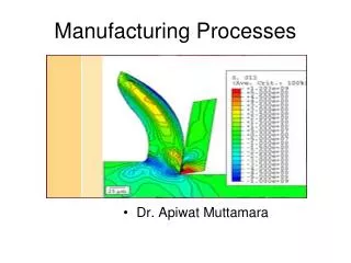
Manufacturing Processes Chapters 5: Bulk Deformation Processes in Metal Working Dr. Yazan Al-Zain Department of Industrial Engineering University of Jordan, Amman-Jordan
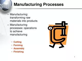
Introduction • Bulk deformation processes in metal working include: • Rolling. • Other deformation processes related to rolling. • Forging. • Other deformation processes related to forging. • Extrusion. • Wire and Bar Drawing.
Introduction • Bulk deformation processes accomplish significant shape change in metal parts whose initial form is bulk rather than sheet. • The starting forms include (1) cylindrical bars and billets, (2) rectangular billets and slabs, and (3) similar elementary geometries. • The bulk deformation processes refine the starting shapes, sometimes improving mechanical properties, and always adding commercial value. • Deformation processes work by stressing the metal sufficiently to cause it to plastically flow into the desired shape.
Introduction • Bulk deformation processes are performed as (1) cold, (2) warm, and (3) hot working operations. • Cold and warm working is appropriate when the shape change is less severe, and there is a need to improve mechanical properties and achieve good finish on the part. • Hot working is generally required when massive deformation of large workparts is involved.
Introduction • The commercial and technological importance of bulk deformation processes derives from the following: • When performed as hot working operations, they can achieve significant change in the shape of the workpart. • When performed as cold working operations, they can be used not only to shape the product, but also to increase its strength through strain hardening. • These processes produce little or no waste as a byproduct of the operation. Some bulk deformation operations are near net shape or net shape processes; they achieve final product geometry with little or no subsequent machining.
Rolling • Rolling: is a deformation process in which the thickness of the work is reduced by compressive forces exerted by two opposing rolls. • The rolls rotate to pull and simultaneously squeeze the workpart between them. Figure 19.1 The rolling process (specifically, flat rolling).
Rolling • According to the part geometry, the rolling processes can be divided into: • Flat rolling: used to reduce the thickness of a rectangular cross section. • Shape rolling: related to flat rolling, in which a square cross section is formed into a shape such as an I-beam.
Rolling • Rolling can be carried out at high or low (ambient) temperatures. • Hot rolling: most rolling is carried out by hot working, due to the large amount of deformation required. • Hot-rolled metal is generally free of residual stresses, and its properties are isotropic (similar properties in different directions). • Disadvantages of hot rolling are that the product cannot be held to close tolerances, and the surface has a characteristic oxide scale.
Rolling • Rolling can be carried out at high or low (ambient) temperatures. • Cold rolling: less common than hot rolling. • Cold rolling strengthens the metal and permits a tighter tolerance on thickness. • the surface of the cold-rolled sheet is absent of scale and generally superior to the corresponding hot-rolled product.
Rolling Figure 19.2 Some of the steel products made in a rolling mill.
RollingFlat Rolling and Its Analysis • Flat rolling involves the rolling of workparts of rectangular cross section in which the width is greater than the thickness; e.g. slabs, strips, sheets and plates. • Draft is amount of thickness reduction and described as: • Draft is sometimes expressed as a fraction of the starting stock thickness, called the Reduction (r): where d = draft, mm; t0= starting thickness, mm; and tf = final thickness, mm.
RollingFlat Rolling and Its Analysis Figure 19.3 Side view of flat rolling, indicating before and after thicknesses, work velocities, angle of contact with rolls, and other features.
RollingFlat Rolling and Its Analysis • Spreading: the increase in width due to rolling, described as: • Similarly, before and after volume rates of material flow must be the same, so the before and after velocities can be related: where wo and wf are the before and after work widths, mm; and Lo and Lf are the before and after work lengths, mm. where vo and vf are the entering and exiting velocities of the work.
RollingFlat Rolling and Its Analysis • True strain is expressed by: • The true strain can be used to determine the average flow stress Yf (MPa)applied to the work material in flat rolling: The average flow stress is used to compute estimates of force and power in rolling.
RollingFlat Rolling and Its Analysis • There is a limit to the maximum possible draft that can be accomplished in flat rolling with a given coefficient of friction, defined by: • Rolling force (F, N) can be expressed as: • Contact length (L, mm) is described as: • The torque (T) and the power required to drive each roll (P, J/s) are: where dmax = maximum draft, mm; μ = coefficient of friction; and R = roll radius, mm. and where P = power, J/s or W; N = rotational speed, 1/s; F = rolling force, N; and L = contact length, m.
RollingShape Rolling • In shape rolling, the work is deformed into a contoured cross section. • Products include construction shapes such as I-beams, L-beams, and U-channels; rails for railroad tracks; and round and square bars and rods. • The process is accomplished by passing the work through rolls that have the reverse of the desired shape. • Most of the principles that apply in flat rolling are also applicable to shape rolling. • Shaping rolls are more complicated; and the work, usually starting as a square shape, requires a gradual transformation through several rolls in order to achieve the final cross section.
RollingRolling Mills • Rolling mill configurations: • Two-high: consists of two opposing rolls, and the configuration can be either reversing or nonreversing. Figure 19.4 Various configurations of rolling mills: (a) two-high rolling mill.
RollingRolling Mills • Rolling mill configurations: • Three-high: three rolls in a vertical column, and the direction of rotation of each roll remains unchanged. Figure 19.4 Various configurations of rolling mills: (b) three-high rolling mill.
RollingRolling Mills • Rolling mill configurations: • Four-high: uses two smaller-diameter rolls to contact the work and two backing rolls behind them. Figure 19.4 Various configurations of rolling mills: (c) four-high rolling mill.
RollingRolling Mills • Rolling mill configurations: • Cluster mill: roll configuration that allows smaller working rolls against the work (smaller than in four-high mills). Figure 19.4 Various configurations of rolling mills: (d) cluster mill.
RollingRolling Mills • Rolling mill configurations: • Tandem rolling mill : consists of a series of rolling stands, aimed at higher throughput rates. Figure 19.4 Various configurations of rolling mills: (e) tandem rolling mill.
Other Deformation Processes Related to Rolling • Thread Rolling: • Used to form threads on cylindrical parts by rolling them between two dies. • The most important commercial process for mass producing external threaded components. • Performed by cold working in thread rolling machines. These are equipped with special dies that determine the size and form of the thread. • Advantages of thread rolling over thread cutting and rolling include: • Higher production rates. • Better material utilization. • Smoother surface. • Stronger threads and better fatigue resistance due to work hardening.
Other Deformation Processes Related to Rolling • Thread Rolling: Figure 19.5 Thread rolling with flat dies: (1) start, and (2) end of cycle.
Other Deformation Processes Related to Rolling • Ring Rolling: a deformation process in which a thick-walled ring of smaller diameter is rolled into a thin-walled ring of larger diameter. • As the thick-walled ring is compressed, the deformed material elongates, causing the diameter of the ring to be enlarged. Figure 19.6 Ring rolling used to reduce the wall thickness and increase the diameter of a ring: (1) start, and (2) completion of process.
Other Deformation Processes Related to Rolling • Ring Rolling: • Usually performed as a hot-working process for large rings and as a cold-working process for smaller rings. • Applications include ball and roller bearing races, steel tires for railroad wheels, and rings for pipes, pressure vessels, and rotating machinery. • Advantages over processes producing similar products include: (1) raw material savings, (2) ideal grain orientation for the application, and (3) strengthening through cold working.
Other Deformation Processes Related to Rolling • Roll Piercing: a specialized hot working process for making seamless thick-walled tubes. • Based on the principle that when a solid cylindrical part is compressed on its circumference, high tensile stresses are developed at its center. If compression is high enough, an internal crack is formed. • Compressive stresses on a solid cylindrical billet are applied by two rolls, whose axes are oriented at slight angles (6º) from the axis of the billet, so that their rotation tends to pull the billet through the rolls. A mandrel is used to control the size and finish of the hole created by the action.
Other Deformation Processes Related to Rolling • Roll Piercing: Figure 19.7 Roll piercing: (a) formation of internal stresses and cavity by compression of cylindrical part; and (b) setup of Mannesmann roll mill for producing seamless tubing.
Forging • Forging: a deformation process in which the work is compressed between two dies, using either impact or gradual pressure to form the part. • Dates back to perhaps 5000 BCE. • Today, forging is an important industrial process used to make a variety of high-strength components for automotive, aerospace, and other applications. • These components include engine crankshafts and connecting rods, gears, aircraft structural components, and jet engine turbine parts. • In addition, steel and other basic metals industries use forging to establish the basic form of large components that are subsequently machined to final shape and dimensions.
Forging • Forging can be classified in many ways, one is working temperature. • Hot or warm forging: done when significant deformation is demanded by the process and when strength reduction and increase of ductility is required. • Cold forging: its advantage is the increased strength that results from strain hardening of the component. • The other way is by the way the forging is carried out: • Forging hammer: a forging machine that applies an impact load. • Forging press: a forging machine that applies gradual load.
Forging • Forging can be also classified according to the degree to which the flow of the work metal is constrained by the dies. • Open-die forging: the work is compressed between two flat dies, thus allowing the metal to flow without constraint in a lateral direction relative to the die surfaces. • Impression-die forging: the die surfaces contain a shape or impression that is imparted to the work during compression, thus constraining metal flow to a significant degree. Here, flash will form. • Flashless forging: the work is completely constrained within the die and no excess flash is produced.
Forging Figure 19.8 Three types of forging operation: (a) open-die forging, (b) impression-die forging, and (c) flashless forging.
ForgingOpen-Die Forging • Known as upsetting or upset forging. • Involves compression of a workpart of cylindrical cross section between two flat dies, much in the manner of a compression test. • It reduces the height of the work and increases the diameter.
ForgingOpen-Die Forging • Analysis of Open-Die Forging: • If carried out under ideal conditions of no friction between work and die surfaces, then homogeneous deformation occurs, and the flow of the material is uniform throughout its height. Figure 19.9 Homogeneous deformation of a cylindrical workpart under ideal conditions in an open‑die forging operation: (1) start of process with workpiece at its original length and diameter, (2) partial compression, and (3) final size.
ForgingOpen-Die Forging • Analysis of Open-Die Forging: • Under these ideal conditions, the true strain experienced by the work during the process can be determined by: • The force to perform upsetting at any height is given by: where F = force, N; A= cross-sectional area, mm2; and Yf = flow stress, MPa.
ForgingOpen-Die Forging • Analysis of Open-Die Forging: • If carried out under conditions where friction between work and die surfaces is accounted for, a barreling effect is created. Figure 19.10 Actual deformation of a cylindrical workpart in open-die forging, showing pronounced barreling: (1) start of process, (2) partial deformation, and (3) final shape.
ForgingOpen-Die Forging • Analysis of Open-Die Forging: • Friction causes the actual upsetting force to be greater than what is predicted the previous equation: where Kfis the forging shape factor, defined as: where μ= coefficient of friction; D = workpart diameter or other dimension representing contact length with die surface, mm; and h = workpart height, mm.
ForgingOpen-Die Forging • In practice, open-die forging can be classified into: • Fullering: a forging operation performed to reduce the cross section and redistribute the metal in a workpart in preparation for subsequent shape forging (dies have convex surfaces). • Edging: similar to fullering, except that the dies have concave surfaces. • Cogging: consists of a sequence of forging compressions along the length of a workpiece to reduce cross section and increase length.
ForgingOpen-Die Forging Figure 19.11 Several open-die forging operations: (a) fullering, (b) edging, and (c) cogging.
ForgingImpression-Die Forging • Impression-die forging (sometimes called closed-die forging): performed with dies that contain the inverse of the desired shape of the part. • As the die closes to its final position, flash is formed by metal that flows beyond the die cavity and into the small gap between the die plates. • Although this flash must be finally cut away, it serves an important function during impression-die forging. • As the flash begins to form, friction resists continued flow of metal into the gap, thus constraining the bulk of the work material to remain in the die cavity. • In hot forging, metal flow is further restricted because the thin flash cools quickly against the die plates, thereby increasing its resistance to deformation. • Accordingly, compression pressure is increased, thus forcing the material to fill the whole cavity.
ForgingImpression-Die Forging • Sequence in impression-die forging: Figure 19.12 Sequence in impression-die forging: (1) just prior to initial contact with raw workpiece, (2) partial compression, and (3) final die closure, causing flash to form in gap between die plates.
ForgingImpression-Die Forging • Advantages of impression-die forging compared to machining from solid stock include: higher production rates, less waste of metal, greater strength and favorable grain orientation in the metal. • Limitations include: the incapability of close tolerances and machining is often required to achieve accuracies and features needed.
ForgingFlashless Forging • Flashless Forging: the raw workpiece is completely contained within the die cavity during compression, and no flash is formed. • Several requirements: • The work volume must equal the space in the die cavity within a very close tolerance. • If the starting blank is too large, excessive pressures may cause damage to the die or press. If the blank is too small, the cavity will not be filled. • Simple geometries required. • Best for soft metals, such as aluminum and cupper and their alloys. • Sometimes classified as Precision Forging.
ForgingFlashless Forging Figure 19.13 Flashless forging: (1) just before initial contact with workpiece, (2) partial compression, and (3) final punch and die closure.
ForgingFlashless Forging • Coining: is a type of flashless forging, in which fine details in the die are impressed into the top and bottom surfaces of the workpart. There is little flow of metal in coining. Figure 19.14 Coining operation: (1) start of cycle, (2) compression stroke, and (3) ejection of finished part.
ForgingForging Hammers and Presses • Equipment used in forging consists of forging machines, classified as hammers or presses, and forging dies. • In addition, auxiliary equipment is needed, such as furnaces to heat the work, mechanical devices to load and unload the work, and trimming stations to cut away the flash in impression-die forging.
ForgingForging Hammers and Presses (1) Forging Hammers: operate by applying an impact loading against the work. They deliver impact energy to the workpiece. • Used for impression-die forging. • The upper portion of the forging die is attached to the ram, and the lower portion is attached to the anvil. • The work is placed on the lower die, and the ram is lifted and then dropped. • When the upper die strikes the work, the impact energy causes the part to assume the form of the die cavity. • Several blows of the hammer are often required to achieve the desired change in shape.
ForgingForging Hammers and Presses • Forging hammers are classified into: • Gravity drop hammers: achieve their energy by the falling weight of a heavy ram, and the force of the blow is determined by the height of the drop and the weight of the ram. • Power drop hammers: accelerate the ram by pressurized air or steam. • Disadvantage: a large amount of the impact energy is transmitted through the anvil and into the floor of the building.
ForgingForging Hammers and Presses Figure 19.15 Diagram showing details of a drop hammer for impression‑die forging.
ForgingForging Hammers and Presses (2) Forging Presses: apply gradual pressure, rather than sudden impact, to accomplish the forging operation. • Include mechanical presses, hydraulic presses, and screw presses. • Mechanical presses convert the rotating motion of a drive motor into the translation motion of the ram. • Hydraulic presses use a hydraulically driven piston to drive the ram. • Screw presses apply force by a screw mechanism that drives the vertical ram.
Other Deformation Processes Related to Forging • Upsetting and Heading: a deformation operation in which a cylindrical workpart is increased in diameter and reduced in length. • Used in the fastener industry to form heads on nails, bolts, etc (in these applications, it is referred to as heading). • More parts produced by upsetting than any other forging operation. • Performed cold, hot or warm on special upset forging machines, called headers or formers. • Long wire is fed into the machines, the end of the stock is upset forged, and then the piece is cut to length to make the desired hardware item.