Download
1 / 59
600 likes | 633 Views
Optical Fibre Communication Systems. Lecture 3: Light Sources. Professor Z Ghassemlooy. Northumbria Communications Laboratory Faculty of Engineering and Environment The University of Northumbria U.K. http://soe.unn.ac.uk/ocr. Contents. Properties Types of Light Source LED Laser

E N D
Optical Fibre Communication Systems Lecture 3: Light Sources Professor Z Ghassemlooy Northumbria Communications Laboratory Faculty of Engineering and Environment The University of Northumbria U.K. http://soe.unn.ac.uk/ocr
Contents • Properties • Types of Light Source • LED • Laser • Types of Laser Diode • Comparison • Modulation • Modulation Bandwidth
Light Sources - Properties In order for the light sources to function properly and find practical use, the following requirements must be satisfied: • Output wavelength: must coincide with the loss minima of the fibre • Output power: must be high, using lowest possible current and less heat • High output directionality: narrow spectral width for coupling to fibre • Wide bandwidth • Low distortion • Easy to modulate • Low cost
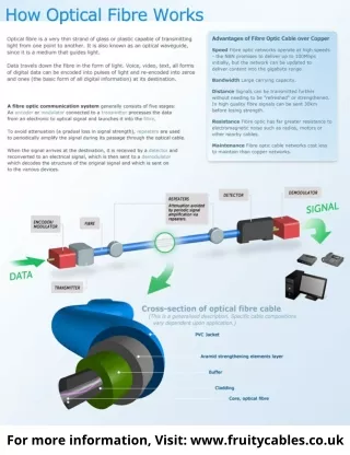
Light Sources - Types Every day light sources such as tungsten filament and arc lamps are suitable, but there exists two types of devices, which are widely used in optical fibre communication systems: Light Emitting Diode (LED) Semiconductor Laser Diode (SLD or LD). In both types of device the light emitting region consists of a pn junction constructed of a direct band gap III-V semiconductor, which when forward biased, experiences injected minority carrier recombination, resulting in the generation of photons.
p n Electron --- Fermi levels Hole Homojunction LED LED - Structure • pn-junction in forward bias, • Injection of minority carriers across the junction gives rise to efficient radiative recombination (electroluminescence) of electrons (in CB) with holes (in VB)
Pt Fibre n-type p-type Hole (+) Electron (-) P0 Narrowed Depletion region I + - LED - Structure • Spontaneous emission • Optical power produced by the Junction: Photons P0 Where int = Internal quantum efficiency q = Electron charge 1.602 x 10⁻¹⁹ C
It considers the number of photons actually leaving the LED structure LED - External quantum efficiency ext Where F = Transmission factor of the device-external interface n = Light coupling medium refractive index nx = Device material refractive index Loss mechanisms that affect the external quantum efficiency: (1) Absorption within LED(2) Fresnel losses: part of the light gets reflected back, reflection coefficient: R={(n2-n1)/(n2+n1)}(3) Critical angle loss: all light gets reflected back if the incident angle is greater than the critical angle.
External power efficiency • MMSF: The coupling efficiency • GMMF: Or the power coupled to the fibre: The optical coupling loss relative to Peis: • Emitted optical power LED - PowerEfficiency
LED- Tyeps Surface Emitting LED (SLED) Edge Emitting LED (ELED) • Data rates less than 20 Mbps • Short optical links with large NA fibres (poor coupling) • Coupling lens used to increase efficiency • Higher data rate > 100 Mbps • Multimode and single mode fibres G Keiser 2000
1300-1550 nm Intensity 800-900 nm 0 65 45 45 65 15 15 Wavelength (nm) LED - Spectral Profile
SELED Temperature Linear region 5 4 ELED 3 Power P0 (mW) 50 2 Current I (mA) 1 LED - Power Vs. Current Characteristics • Output power decreases with age, Life time of 105 hours • i.e. 3dB drop in optical • power Since P I, then LED can be intensity modulated by modulating the I
LED - Characteristics Wavelength 800-850 nm 1300 nm • Spectral width (nm) 30-60 50-150 • Output power (mW) 0.4-5 0.4-1.0 • Coupled power (mW) - 100 um core 0.1-2 ELED 0.3-0.4 SLED 0.04-0.08 - 50 um core 0.01-0.05 SLED 0.05-0.15 0.03-0.07 - Single mode 0.003-0.04 • Drive current (mA) 20-150 100-150 • Modulation bandwidth 80-150 100-300 (MHz) Operating temperature -650 to 1250
Laser - Characteristics • The term Laser stands forLight Amplification by Stimulated Emission of Radiation. • Is an optical oscillator - Comprises a resonant optical amplifier whose output is fed back into its input with matching phase. Any oscillator contains: • An amplifier with a gain-saturated mechanism • A feedback system • A frequency selection mechanism • An output coupling scheme • Could be mono-chromatic (one colour), and is coherent in nature. (I.e. all the wavelengths contained within the Laser light have the same phase). One the main advantage of Laser over other light sources • A pumping source providing power • It had well defined threshold current beyond which lasing occurs • At low operating current it behaves like LED • Most operate in the near-infrared region
mirror 1 mirror 2 coherent light Mirrors used to “re-cycle” phonons” “LED” R = 0.90 R = 0.99 Laser - Basic Operation Similar to LED, but based onstimulated light emission. Reflectivity R = [(n-1)/(n+1)]2 Three steps required to generate a laser beam are: • Absorption • Spontaneous Emission • Stimulated Emission • Current density: • 104 A/cm2 down to 10 A/cm2
E2 E2 E1 E1 Initial state E2 E1 Excited electron final state Absorption When a photon with certain energy is incident on an electron in a semiconductor at the ground state(lower energy level E1 the electron absorbs the energy and shifts to the higher energy level E2. The energy now acquired by the electron is Ee = hf = E2 - E1. Plank's law Incoming photon Ee = hf Electron
E2 E2 Photon E1 E1 Initial state Spontaneous Emission • E2 is unstable and the excited electron(s) will return back to the lower energy level E1 • As they fall, they give up the energy acquired during absorption in the form of radiation, which is known as the spontaneous emission process. Ee = hf
E2 E2 Coherent light E1 E1 Stimulated Emission • But before the occurrence of this spontaneous emission process, if external stimulation (photon) is used to strike the excited atom then, it will stimulate the electron to return to the lower state level. • By doing so it releases its energy as a new photon. The generated photon(s) is in phase and have the same frequency as the incident photon. • The result is generation of a coherent light composed of two or more photons. • In quantum mechanic – Two process: Absorption and Stimulated emission Ee = hf Ee = hf Ee = hf Ee = hf Requirement: <0 Light amplification: I(x) = I0exp(-x)
Laser - Basic Operation So we have a large number of electron inside a cavity, therefore need to talk about statistics. Thus need to talk average rates of transition. I.e. what is the probability that a transition can take place between two levels per unit time. N2 The rate of absorption process is: Photon density In the cavity foe E21 Transition probability from 1 to 2 [is a constant introduced by Einstein] Occupation probability of level 1 Probability that Lower level is empty f1 and f2 are Fermi functions given as: F1 and F2 are quasi Fermi levels (i.e., number of electrons in the lower and upper levels, respectively
Laser - Basic Operation The rate of spontaneous emission process is: Probability that Lower level is empty Transition probability from 2 to 1 [is a constant introduced by Einstein] Occupation probability of level 2 The rate of stimulated emission process is: Photon density In the cavity foe E21 Transition probability from 2 to 1 The rate of total emission process is (upper level is depopulated):
Laser - Basic Operation • At dynamic equilibrium Absorption = emission One need to solve this to determine
Rate of change of photon numbers Rate of change of electron numbers = stimulated emission + spontaneous emission + loss = Injection + spontaneous emission + stimulated spontaneous The Rate Equations N is photons per unit volume (optical output power), J is the current density, Rspis the rate of spontaneous emission, ph photon life time, d depth of the active Region, sp spontaneous recombination rate, C is the constant, ne injected electron per unit volume At the threshold, N = 0, dN/dt >=0, and Rsp ~ 0, so ne >= 1/Cph= n Andd ne /dt= 0, thus J = qdn/ph
The Rate Equations • At the threshold, we have • N = 0, dN/dt >=0, • and Rsp ~ 0, • so ne >= 1/Cph= nth • Andd ne /dt= 0, • thus Jth = qdn/ph • Beyond the threshold, we have • J> Jth • So
I Standing wave (modes) exists at frequencies for which L i = 1, 2, .. Modes are separated by Optical confinement layers In terms of wavelength separation (Longitudinal mode spacing) Laser Diodes (LD) Z=0 Z=L
Input Current Ib=0 Output Light Signal Ib=0.5Ith Turn on Delay (ns) Ib=0.9Ith d LD – Turn–on Delay To reduce the turn on delay: • Use a low threshold laser and make Ip large • Bias the laser at or above threshold
Modes Intensity 0 5 3 3 5 1 1 Wavelength (nm) LD - Spectral Profile Gaussian output profile Multi-mode
LD - Efficiencies Internal quantum efficiency External quantum efficiency External power efficiency Where P = IV Power degradation over time Lifetime decreases with current density and junction temperature
Temp. LED 5 Stimulated emission (lasing) 4 3 Spontaneous emission Power P0 (mW) 2 Threshold current Ith 50 1 Current I (mA) Power Vs. Current Characteristics • Applying a bias current has the same effect as applying a pump laser; electrons are promoted to conduction band. Fc and Fv get farther apart as well • Increasing the temperature creates a population distribution rather than a sharp cutoff near the Fermi levels • For LD: Slope efficiency = P0/(I – Ith)
LD – Electrical Model Simple large signal model Package Lead Inductance Bond wire Inductance Laser contact resistance Use a large signal diode model for the laser junction, this neglects the optical resonance Package Lead Capacitance Laser Junction Laser Pad Capacitance More exactly the laser rate equations can be implemented in SPICE to give the correct transient behavior under large signal modulation Assume that the light output is proportional to the current through the laser junction Small signal model (Hitachi)
LD - Single Mode • Achieved by reducing the cavity length L from 250 m to 25 m • But difficult to fabricate • Low power • Long distance applications Types: • Fabry-Perot (FP) • Distributed Feedback (DFB) • Distributed Bragg Reflector (DBR) • Distributed Reflector (DR)
P Threshold I 250-500 um Cleaved faces 5-15 um Laser - Fabry-Perot • Strong optical feedback in the longitudinal direction • Multiple longitudinal mode spectrum • “Classic” semiconductor laser • 1st fibre optic links (850 nm or 1300 nm) • Short & medium range links • Key characteristics • Wavelength: 850 or 1310 nm • Total output power: a few mw • Spectral width: 3 to 20 nm • Mode spacing: 0.7 to 2 nm • Highly polarized • Coherence length: 1 to 100 mm • Small NA ( good coupling into fiber) Ppeak Agilent Technology
P peak SMSR Corrugated feedback Bragg Laser - Distributed Feedback (DFB) • No cleaved faces, uses Bragg Reflectors for lasing • Single longitudinal mode spectrum • High performance • Costly • Long-haul links & DWDM systems • Key characteristics • Wavelength: around 1550 nm • Total power output: 3 to 50 mw • Spectral width: 10 to 100 MHz (0.08 to 0.8 pm) • Sidemode suppression ratio (SMSR): > 50 dB • Coherence length: 1 to 100 m • Small NA ( good coupling into fiber) Agilent Technology
Laser output p-DBR active n-DBR Laser - Vertical Cavity Surface Emitting Lasers (VCSEL) • Distributed Bragg reflector mirrors • Alternating layers of semiconductor material • 40 to 60 layers, each l / 4 thick • Beam matches optical acceptance needs of fibers more closely • Key properties • Wavelength range: 780 to 980 nm (gigabit ethernet) • Spectral width: <1nm • Total output power: >-10 dBm • Coherence length:10 cm to10 m • Numerical aperture: 0.2 to 0.3 Agilent Technology
Spectral width (nm) 1-5 < 0.2 • Output power (mW) 1-10 10-100 • Coupled power (W) - Single mode 0.1-5 1-40 • External quantum efficiency 1-40 25-60 • Drive current (mA) 50-150 100-250 • Modulation bandwidth 2000 6000-40,000 (MHz) Laser diode - Properties Property Multimode Single Mode
LED LD 0 -3 800 nm Single mode Multimode Magnitude (dB) 1300-1550 nm 1 10 100 1000 10,000 Frequency (MHz) LED - Frequenct Response
Comparison (107 Hours)
DC Intensity Modulated optical carrier signal RF modulating signal R I Modulation The process transmitting information via light carrier (or any carrier signal) is called modulation. • Direct Intensity (current) • Inexpensive (LED), but suffer from non-linearity effects • In LD it suffers fromchirp up to 1 nm (wavelength variation due to variation in electron densities in the lasing area) • External Modulation – For higher data rates(> a few Gbps)
Modulation – LED Model • The voltage across of LED Vd+ (IRd) = Vo http://www.prodigit.com/qa_c_3.php?button_num=g8&cnt_id=14
LED LD Input signal Direct Intensity Modulation- Analogue Modulation Index M = I/IB’ For LED IB’ = IB For LD IB’ = IB - Ith With no input signal m(t) the optical output P(t) = Pt[1 + M m(t), G Keiser 2000
Direct Intensity Modulation- Analogue • Simple • Referred to as a transconductance amplifier - converts a V I. • R1: prevents oscillations in Q1. • A drawback – • The base capacitance varies with the base voltage, which introduces nonlinearities that limit the circuits linearity. http://www.fiber-optics.info/articles/light-emitting_diode_led
Direct Intensity Modulation- Analogue • Moderate performance • The linearized eliminates most of the nonlinearities associated with Q1. • U1 forms a feedback loop that drives the base of Q1 in such a way that assures that VR2 equals VIN. • Still experiences some lesser nonlinearities associated with Q1, but these do not represent the limiting factor. • Note, the delay due to the feedback in U1, which limits the bandwidth to about 10-100 MHz. http://www.fiber-optics.info/articles/light-emitting_diode_led
Direct Intensity Modulation- Analogue • Highest performance. • R1 supplies the DC current through D1. Sometimes, a constant current source or a network that includes temperature compensation replaces R1. • A wideband RF amplifier, U1, serves two purposes: • amplifies VIN to allow the use of a small input signal. • isolates the LED from the input circuit, so impedance matching at the input, VIN, which reduces reflections. The output of U1 is usually 50 Ohms or 75 Ohms. • C1 - Block any DC. A typical LED may have an input impedance ranging from 5 Ohms to 10 Ohms. An impedance matching network is inserted between the amplifier and D1. http://www.fiber-optics.info/articles/light-emitting_diode_led
Direct Intensity Modulation- Analogue Q1 is turned on by R1 and acts as a variable resistor. Q2 is an “over-current” switch and R2 sets the maximum current.
Direct Intensity Modulation- Digital http://www.next.gr/light-laser-led/led-circuits/optical-communication-system-l12211.html
Direct Intensity Modulation- Analogue http://circuitsgallery.blogspot.co.uk/2012/06/laser-communication-project-circuit.html
Optical power Optical power i i Time Time t t Direct Intensity Modulation- Analogue • No concern about LED linearity, since the light is either ON or OFF LED LD In a pulse modulated laser, if the laser is completely turned off after each pulse, after onset of the current pulse, a time delay is given by:
Direct Intensity Modulation- Digital • Simple driver circuit. • The transistor is a switch • The key disadvantage – • Low speed. • This type of driver circuit is rarely used at data rates above 30-50 Mb/s. Series drive circuit • Higher speed. • Uses Q1 to quickly discharge the LED to turn it off. • Note: LED's are easy to turn on quickly, but are difficult to turn off because of the relatively long carrier lifetime. • In the shunt driver circuit, R2 (typicall 40- 1k Ohms) provides a positive current to turn on the LED. • Q1 provides the turnoff current. When saturated, Q1 will have an impedance of a few Ohms. This provides a much larger discharging current allowing the LED to turn off quickly. Shunt drive circuit Power dissipation - Double that of the series driver
Direct Intensity Modulation- Digital • Much faster. • C1 - to improve the turn-on and turnoff characteristics of Q1. • C1 should not be too large. If this occurs, Q1 base may be overdriven and damaged. • R3 and R4 and capacitor C2 - Provide overdrive when the LED is turned on and underdrive when Q1 is turned off. • The overdrive and underdrive accelerates the LED transitions. • Typically, the RC time constant of R3 and C2 is made ~ approximately equal to the rise or fall time of the LED.
Monitor Photodiode Laser - Data Vref + -5V Direct Intensity Modulation- Digital Average number of 1s and 0s (the “Mark Density”) is linearly related to the average power. If this duty cycle changes then the bias point will shift
Direct Intensity Modulation- Limitations • Turn on delay and resonance frequency are the two major factors that limit the speed of digital laser modulation • the photon life time in the laser cavity: • the relaxation oscillation frequency given by: • Saturation and clipping introduces nonlinear distortion with analog modulation (especially in multi carrier systems) • Nonlinear distortions introduce higher order inter modulation distortions (IMD3, IMD5…) • Chirp: Unwanted laser output wavelength drift with respect to modulating current that result on widening of the laser output spectrum.
DC MOD Modulated optical carrier signal R I RF (modulating signal) External Modulation • For high frequencies 2.5 Gbps - 40 Gbps, and is more complex, higher performance. • AM sidebands (caused by modulation spectrum) dominate linewidth of optical signal