Download
1 / 60
600 likes | 615 Views
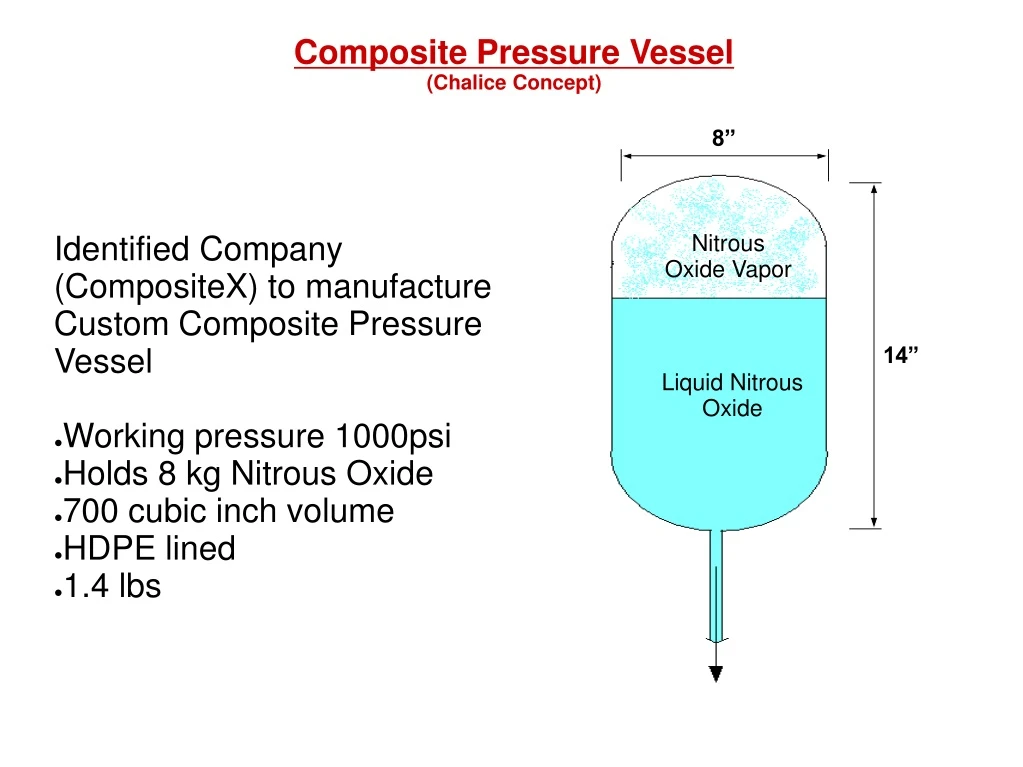
Composite Pressure Vessel (Chalice Concept). Nitrous Oxide Vapor. Liquid Nitrous Oxide. Identified Company (CompositeX) to manufacture Custom Composite Pressure Vessel Working pressure 1000psi Holds 8 kg Nitrous Oxide 700 cubic inch volume HDPE lined 1.4 lbs.

E N D
Composite Pressure Vessel(Chalice Concept) Nitrous Oxide Vapor Liquid Nitrous Oxide • Identified Company (CompositeX) to manufacture Custom Composite Pressure Vessel • Working pressure 1000psi • Holds 8 kg Nitrous Oxide • 700 cubic inch volume • HDPE lined • 1.4 lbs
Composite Pressure Vessel(Chalice Concept) Helium Gas Liquid Nitrous Oxide
Composite Pressure Vessel(Chalice Concept) • Ideal gas law used to model helium pressure • p=m*R*T/V • Verified from pressure/ temperature data that Helium will remain gaseous • Compressibility factor ~1, so ideal gas assumption valid • Tank weights listed estimated from quote of 700ci=1.4 lbs • Also includes weight of Helium (case dependent)
Mass CalculationChalice Design, 7075-T6 Al240mm OD, 1.75mm Thickness, FS 1.25
Mass CalculationEmbedded Outer Shell Design, 7075-T6 Al 180mm OD, 61mm ID, 1.3mm Thickness, FS 1.25
Mass CalculationEmbedded Inner Shell Design, Grade 5 Titanium61mm OD, 0.5mm Thickness
Inner and Outer Shell ANSYS Stress Modeling(Embedded Fuel Grain Concept) Model Geometry Inner Shell (fuel grain housing) Outer radius: 2.40” (~61mm) Inner radius: 2.36” (~60mm) Height: 21.46” (~545 m) Mat’l: Aluminum 7075 T6 Outer Shell (NOS/rocket housing) Outer radius: 1.75” + 0.5 mm (0.03225 m) Inner radius: 1.25” (0.03175 m) Height: 1.5” (0.0381 m) Mat’l: Al 7075 T6 with Composite over-wrap Composite: IM7 Carbon (fiber) / PEEK (matrix)
Inner and Outer Shell ANSYS Stress Modeling(Embedded Fuel Grain Concept) Material Properties Carbon/PEEK Composite (Modeled as Isotropic) Density: 1600 kg/m3 Longitudinal Mod., E1: 71.7e9 Pa Transverse Mod., E2: 10.2e9 Pa Poisson’s Ratio, v12: 0.30 Shear Modulus, G12: 5.7e9 Al 7075-T6 (Modeled as Isotropic) Density: 2810 kg/m3 Longitudinal Mod., E1: 71.7e9 Pa Poisson’s Ratio, v12: 0.33 PEEK (matrix) Density: 1376 kg/m3 IM7 Carbon Fiber (12,000 filaments) (Modeled as Orthotropic) Density: 1780 kg/m3 Longitudinal Mod., E1: 278e9 Pa Poisson’s Ratio, v12: 0.20
Inner and Outer Shell ANSYS Stress Modeling(Embedded Fuel Grain Concept) Outer Shell (w/ composite) Figure 1: Outer Shell of Imbedded Fuel Grain Design (Meshed Elements – 8node93)
Inner and Outer Shell ANSYS Stress Modeling(Embedded Fuel Grain Concept) Outer Shell (w/ composite) Figure 2: Outer Shell of Imbedded Fuel Grain Design: Plot Results Contour Plot Element Solution Stresses von Mises stress
Inner and Outer Shell ANSYS Stress Modeling(Embedded Fuel Grain Concept) Outer Shell (w/ composite) Figure 3: Outer Shell of Imbedded Fuel Grain Design: Plot Results Deformed Shape Def + undeformed
Inner and Outer Shell ANSYS Stress Modeling(Embedded Fuel Grain Concept) Outer Shell (w/ composite) Figure 4: Outer Shell of Imbedded Fuel Grain Design: (Pressure & Constraints – Rotated view)
Inner and Outer Shell ANSYS Stress Modeling(Embedded Fuel Grain Concept) Outer Shell (w/ composite) Figure 5: Outer Shell of Imbedded Fuel Grain Design: (Pressure & Constraints - Front View)
Inner and Outer Shell ANSYS Stress Modeling(Embedded Fuel Grain Concept) Outer Shell (w/ composite) Figure 6: Outer Shell of Imbedded Fuel Grain Design: (Pressure & Constraints - Side View)
Inner and Outer Shell ANSYS Stress Modeling(Embedded Fuel Grain Concept) Inner Shell (All Aluminum) Figure 7: Inner Shell of Imbedded Fuel Grain Design (Meshed Elements – 8node93)
Inner and Outer Shell ANSYS Stress Modeling(Embedded Fuel Grain Concept) Inner Shell (All Aluminum) Figure 8: Inner Shell of Imbedded Fuel Grain Design: Plot Results Contour Plot Element Solution Stresses von Mises stress
Inner and Outer Shell ANSYS Stress Modeling(Embedded Fuel Grain Concept) Inner Shell (All Aluminum) Figure 9: Inner Shell of Imbedded Fuel Grain Design: Plot Results Deformed Shape Def + undeformed
Inner and Outer Shell ANSYS Stress Modeling(Embedded Fuel Grain Concept) Inner Shell (All Aluminum) Figure 10: Inner Shell of Imbedded Fuel Grain Design: (Pressure & Constraints – Rotated view)
Inner and Outer Shell ANSYS Stress Modeling(Embedded Fuel Grain Concept) Inner Shell (All Aluminum) Figure 11: Inner Shell of Imbedded Fuel Grain Design: (Pressure & Constraints – Front view)
Inner and Outer Shell ANSYS Stress Modeling(Embedded Fuel Grain Concept) Inner Shell (All Aluminum) Figure 12: Inner Shell of Imbedded Fuel Grain Design: (Pressure & Constraints – Side view)
Inner and Outer Shell ANSYS Stress Modeling(Embedded Fuel Grain Concept) Outer Shell (Aluminum only) Figure 13: Outer Shell of Imbedded Fuel Grain Design (Meshed Elements – 8node93)
Inner and Outer Shell ANSYS Stress Modeling(Embedded Fuel Grain Concept) Outer Shell (Aluminum only) Figure 14: Outer Shell of Imbedded Fuel Grain Design: Plot Results Contour Plot Element Solution Stresses von Mises stress
Inner and Outer Shell ANSYS Stress Modeling(Embedded Fuel Grain Concept) Outer Shell (Aluminum only) Figure 15: Outer Shell of Imbedded Fuel Grain Design: Plot Results Deformed Shape Def + undeformed
Inner and Outer Shell ANSYS Stress Modeling(Embedded Fuel Grain Concept) Outer Shell (Aluminum only) Figure 16: Outer Shell of Imbedded Fuel Grain Design: (Pressure & Constraints – Rotated view)
Inner and Outer Shell ANSYS Stress Modeling(Embedded Fuel Grain Concept) Outer Shell (Aluminum only) Figure 17: Outer Shell of Imbedded Fuel Grain Design: (Pressure & Constraints - Front View)
Inner and Outer Shell ANSYS Stress Modeling(Embedded Fuel Grain Concept) Outer Shell (Aluminum only) Figure 18: Outer Shell of Imbedded Fuel Grain Design: (Pressure & Constraints - Side View)
Inner and Outer Shell ANSYS Stress Modeling(Embedded Fuel Grain Concept) Figure 19: ELEMENT LAYERS
Inner and Outer Shell ANSYS Stress Modeling(Embedded Fuel Grain Concept) Figure 20: LAYER ORIENTATION AND THICKNESS
Inner and Outer Shell ANSYS Stress Modeling(Embedded Fuel Grain Concept) Figure 21: LAYER ORIENTATION AND THICKNESS continued…
Inner and Outer Shell ANSYS Stress Modeling(Embedded Fuel Grain Concept) Figure 22: COMPOSITE PROPERTIES
Inner and Outer Shell ANSYS Stress Modeling(Embedded Fuel Grain Concept) Figure 23: ALUMINUM PROPERTIES
Inner and Outer Shell ANSYS Stress Modeling(Embedded Fuel Grain Concept) Figure 24: FAILURE CRITERIA FOR COMPOSITES
Inner and Outer Shell ANSYS Stress Modeling(Embedded Fuel Grain Concept) Figure 25: INVERSE TSAI-WU STRENGTH RATIO INDEX
Inner and Outer Shell ANSYS Stress Modeling(Embedded Fuel Grain Concept) Figure 26: X-COMP OF STRESS
Inner and Outer Shell ANSYS Stress Modeling(Embedded Fuel Grain Concept) Figure 27: Y-COMP OF STRESS
Inner and Outer Shell ANSYS Stress Modeling(Embedded Fuel Grain Concept) Figure 28: X-COMP OF STRESS
Inner and Outer Shell ANSYS Stress Modeling(Embedded Fuel Grain Concept) Figure 29: SHEAR XY-DIR
Inner and Outer Shell ANSYS Stress Modeling(Embedded Fuel Grain Concept) Figure 30: SHEAR YZ-DIR
Inner and Outer Shell ANSYS Stress Modeling(Embedded Fuel Grain Concept) Figure 31: SHEAR XZ-DIR
Top and Bottom Fixture Solidworks Stress Model(Embedded Fuel Grain Concept) Model Geometry Geometry is the same for both the top and bottom fixture Mass = 0.520526 kg Volume = 0.00018 m3
Top and Bottom Fixture Solidworks Stress Model(Embedded Fuel Grain Concept) 1000 psi 1000 psi Material Properties, Loading, and Meshing Al 7075-T6 Density: 2810 kg/m3 Modulus of Elasticity: 71.7 GPa Shear Modulus: 28 GPa Meshing done with Solidworks and Cosmos finite element analysis Elements: 25306 Nodes: 49277
Top and Bottom Fixture Solidworks Stress Model(Embedded Fuel Grain Concept) Factor of Safety Results
Top and Bottom Fixture Solidworks Stress Model(Embedded Fuel Grain Concept) Discussion of Results • This model demonstrates how the top and bottom fixtures will hold up against the required loads. The loading is purely theoretical at this point, but the model is made, and all that needs to be done is substitute the correct loads for the theoretical ones.
External Shell Solidworks Stress Model(Embedded Fuel Grain Concept) Model Geometry Mass = 1.63918 kg Volume = 0.00058 m3
External Shell Solidworks Stress Model(Embedded Fuel Grain Concept) Material Properties, Loading, and Meshing Al 7075-T6 Density: 2810 kg/m3 Modulus of Elasticity: 71.7 GPa Shear Modulus: 28 GPa 1000 psi Meshing done with Solidworks and Cosmos finite element analysis Elements: 43804 Nodes: 87448
External Shell Solidworks Stress Model(Embedded Fuel Grain Concept) Factor of Safety Results
External Shell Solidworks Stress Model(Embedded Fuel Grain Concept) Discussion of Results
Internal Shell Solidworks Stress Model(Embedded Fuel Grain Concept) Model Geometry Mass = 5.64597 kg Volume = 0.002 m3