Download
1 / 31
310 likes | 437 Views
Consider the current, I, in the line – if V is sinusoidal, I must also be sinusoidal (if we are working in a linear system, I V ) hence the total current will have the same form as the total voltage: V = V 1 e j w t e -g x + V 2 e j w t e +g x (1)

E N D
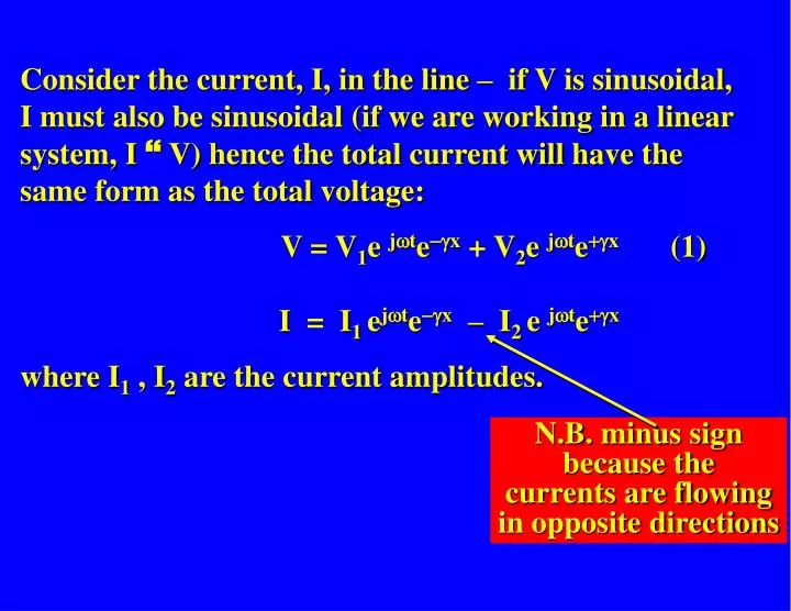
Consider the current, I, in the line – if V is sinusoidal, I must also be sinusoidal (if we are working in a linear system, I V) hence the total current will have the same form as the total voltage: V = V1e jwte-gx + V2e jwte+gx (1) I = I1 ejwte-gx – I2 e jwte+gx where I1 , I2 are the current amplitudes. N.B. minus sign because the currents are flowing in opposite directions
Hence: Note that Zo is NOT per unit length - units are just W. The forward and backward current waves (I+, I-) are related to the respective forward and backward voltage waves (V+, V-) by the CHARACTERISTIC IMPEDANCE, Zo.
Characteristic Impedance of a Lossless Line For a lossless line R=0 and G=0 hence: In the lossless case, Zo is purely REAL, i.e. resistive. Characteristic Impedance of a General Transmission Line If the losses are small, i.e. R << w L and G << w C then Zo can be approximated by:
Reflections on Transmission Lines q Like other waves, voltage and current waves on transmission lines can be reflected. • They are reflected by discontinuities on the line, e.g. the load at the end of the line or a changeover from one type of line to another. • A transmission line with discontinuities will have backward (or reflected) waves when a forward wave is propagated along it. ZL ~
INFINITELY LONG TRANSMISSION LINES If we have a forward wave propagating down a transmission line of finite length, any discontinuities present on the line will give rise to reflections, i.e. backward waves. But for an infinite, uniform transmission line there are no discontinuities and so no reflections - the total voltage and total current at any point on the line (including the input end) will be given by: So the infinite line just looks like a load Zo to the source: I I Zo V V Characteristic impedance Zo
How can the reflections be prevented? Previously we have seen that (a) an infinite transmission line of characteristic impedance Zo behaves as an effective load of impedance Zo . (b) there are no reflections on an infinite transmission line. A B finite A length B infinite Zo Zo Zo Zo Hence, for no reflections and maximum power transfer a line of characteristic impedance Zo should be terminated in a load Zo . In this case the load and line are said to be MATCHED.
Part 2 - Characteristic Impedance and Reflections Lecture Topics 4. Current and voltage on a transmission line: Characteristic impedance, ZO Characteristic impedance of lossless lines Characteristic impedance of general lines Infinitely long transmission lines Reflections on transmission lines 5. Transmission line with change of ZO: voltage reflection coefficient Voltage reflection coefficient at an arbitrary distance l from the load ZL 6. Impedances of terminated lines Voltage Standing Wave Ratio (VSWR) Voltage Standing Wave measurement
Transmission Line with Change of Zo Consider a composite transmission line made up of two sections: a section with characteristic impedance Z1, followed by an infinite line with characteristic impedance Z2: I1+LINE 1 I1- x = 0 LINE 2 I2+ V1+ V1- V2+ to infinity characteristic impedance Z1 characteristic impedance Z2 The section of line with characteristic impedance Z1 will have a backward wave as well as a forward wave because of the reflection caused by the discontinuity. The infinite section (with characteristic impedance Z2) will have only a forward wave.
Expressions for forward and reflected waves on a transmission line
Labelling the waves: V1+ = Vi e-g1x ejwt Superscript label indicates whether this is a forward (+) or backward (-) wave sign of g must correspond to wave direction ( - for forward, + for backward) Subscript labels the different amplitudes: i = incident, r = reflected, t = transmitted Subscript indicates which line we are dealing with: 1 for line 1, 2 for line 2
I1+ LINE 1 I1- x = 0 LINE 2 I2+ V1+ V1- V2+ to infinity We can write down equations for all six of the waves on the composite line: For the forward V1+ = Vi e-g1x ejwt waves on line 1 I1+ = Ii e-g1x ejwt = (Vi /Z1) e-g1x ejwt (since Ii = Vi/Z1) characteristic impedance Z1 characteristic impedance Z2
I1+ LINE 1 I1- x = 0 LINE 2 I2+ V1+ V1- V2+ to infinity For the reflected V1- = Vr e+g1x ejwt waves on line 1 I1- = Ir e +g1x ejwt = (Vr/Z1) e +g1x ejwt (since Ir = Vr/Z1) characteristic impedance Z1 characteristic impedance Z2
I1+ LINE 1 I1- x = 0 LINE 2 I2+ V1+ V1- V2+ to infinity For the forward V2+ = Vt e-g2x ejwt waves on line 2 I2+ = It e-g2x ejwt = (Vt /Z2) e-g2x ejwt (since It = Vt/Z2) characteristic impedance Z1 characteristic impedance Z2
Forward waves V1+ = Vi e-g1x ejwt on line 1 I1+ = (Vi /Z1) e-g1x ejwt (Ii = Vi/Z1) Reflected waves V1- = Vr e+g1x ejwt on line 1 I1- = (Vr/Z1) e +g1x ejwt (Ir = Vr/Z1) Forward wave V2+ = Vt e-g2x ejwt on line 2 I2+ = (Vt /Z2) e-g2x ejwt (It = Vt/Z2)
At the junction between the lines (x = 0) there must be continuity of current and voltage: LINE 1 I1+ - I1- = I2+LINE 2 V1+ + V1- = V2+ to infinity x = 0 Vi e-g1x ejwt + Vr e +g1x ejwt = Vt e-g2x ejwt Ii e-g1x ejwt – Ir e +g1x ejwt = It e-g2x ejwt ejwt cancels out on both sides egx = 1 for x = 0
At the junction between the lines (x = 0) there must be continuity of current and voltage: LINE 1 I1+ - I1- = I2+LINE 2 V1+ + V1- = V2+ to infinity x = 0 Inserting the expressions for V1+ etc. and putting x = 0: Vt = Vi + Vr (1) It = Ii – Ir (2) But each of the current waves can be expressed in terms of the corresponding voltage waves and characteristic impedance, so (2) can be re-written as Vt /Z2 = Vi /Z1 - Vr /Z1 (3)
Eliminating Vt between equations (1) and (3) Vi + Vr = (Vi - Vr)Z2/Z1 Vr (1 + Z2/Z1) = -Vi (1 - Z2/Z1) Vr /Vi = r = -(1 - Z2/Z1)/(1 + Z2/Z1) = (Z2 - Z1)/(Z2 + Z1) • is the voltage reflection coefficient – it tells us how much of the incident wave is reflected back up the transmission line by the discontinuity.
r = (Z2 - Z1)/(Z2 + Z1) What about the voltage reflection coefficient at the load… An infinite line of characteristic impedance Z2 is equivalent to a load Z2 as far as the "source" (i.e. line 1) is concerned: Z2 Z1 Z2 Z1 infinite Zo ZL So for a line of characteristic impedance Zo connected to a load ZL: r = (ZL - Zo)/(ZL + Zo)
Vr /Vi = r = (ZL - Zo)/(ZL + Zo) The voltage reflection coefficient, r, relates the reflected voltage wave to the incident voltage wave and hence is a measure of the discontinuity seen by the transmission line at the load.
Note that: (1) r is a complex number if ZL (or Zo) is complex (Zo is, however, real for a lossless line). Hence r contains both magnitude and phase information: r = |r|ejf |r| is the magnitude of the reflection coefficient f is the phase of the reflection coefficient (2) The magnitude of r varies between 0 and 1 for all values of ZL between 0 and ∞. (Important result for the Smith Chart) 0 |r| 1
The voltage reflection coefficient can be easily determined for the following 3 special cases: 1. Matched Load: ZL = Zo r = (ZL - Zo)/(ZL + Zo) = 0 (hence Vr = rVi = 0) When ZL = Zo the transmission line is "matched" and r = 0: there is no reflected wave and maximum power transfer occurs.
2. Open Circuit: ZL = ∞ r = (ZL - Zo)/(ZL + Zo) = 1 (hence Vr = rVi = Vi ) When the transmission line is open circuited, ZL = ∞ and r = +1. This is expected, since the power that can be dissipated in an open circuit is zero (power = VI and I = 0) so any wave propagating down the transmission line will have to be totallyreflected. TOTAL voltage and current on a transmission line are given by: Vtotal = V+ + V- Itotal = I+ - I- = V+/ Zo - V- / Zo So a reflection coefficient of +1 causes the voltage at the load to double and the current to cancel to zero, which is consistent with an open circuit.
(3) Short Circuit: ZL = 0 r = (ZL - Zo)/(ZL + Zo) = -1 (hence Vr = rVi = -Vi) When the transmission line is short circuited ZL = 0 and r = -1. Again, the power that can be dissipated in a short circuit is zero (power = VI and V = 0) so any wave propagating down the transmission line will be totally reflected. Since Vtotal = V+ + V- ,V+ must equal -V- for zero volts across the load, i.e. r must be -1.
Example 4.3 - Voltage reflection coefficient. Determine the voltage reflection coefficient, ρ, for a transmission line of characteristic impedance Zo = 75 Ω terminated in a load consisting of a 75 Ω resistor in series with a 100 pF capacitor, at frequencies of 10 MHz and 100 MHz.
Example 4.4 - Voltage reflection coefficient for a load and line combination A transmission line of characteristic impedance Z1 is joined to a line of characteristic impedance Z2 which is terminated in a matched load. A resistance, R, is placed across them at the junction between the lines. Determine an expression for the voltage reflection coefficient, ρ, at the junction.
RATIO OF V-/V+AT AN ARBITRARY DISTANCE l FROM THE LOAD ZL So far, we have derived an expression for V-/V+ at the load, which is taken to be at x = 0. But we can define V-/V+ at an arbitrary distance from the load, i.e. we can work it out for a load-and-line combination. So what is V-/V+ at a distance l down the line in front of the load, i.e. at x = -l ? Zo ZL x = -l x = 0 Forward Wave: V+ = Vi e-gx ejwt Backward Wave: V- = Vr e+gx ejwt => V-/V+= r-l = Vr e-gl ejwt/Vi e+gl ejwt = (Vr/Vi e-2gl) = re-2gl (since Vr/Vi = r)
If the line is lossless gl = jbl , hence: r-l= re-2gl =re-j2bl= |r|ejfe-j2bl = |r|ej(f-2bl) (compare with r = |r|ejf) i.e. the magnitude of the reflection coefficient at x = -l is the same as at x = 0 but its phase changes from f to f - 2bl . An additional phase change of -2bl has been added by the introduction of the length of line, l . This is a very important result for the Smith Chart, which we will be looking at later on.
I1+ LINE 1 I1- x = 0 LINE 2 I2+ V1+ V1- V2+ to infinity Summary q Transmission line with change of Zo characteristic impedance Z1 characteristic impedance Z2 r = Vr/Vi = (Z2 – Z1)/(Z2 + Z1)
Z2 Z1 Z2 Z1 infinite Zo ZL q For a line of characteristic impedance Zo connected to a load ZL: r = Vr/Vi = (ZL - Zo)/(ZL + Zo)
q r contains information both on the magnitude of the reflected wave and on the phase difference produced by the reflection process. In general r is a complex number: r = |r|ejf |r| is the magnitude of the reflection coefficient f is the phase of the reflection coefficient • The magnitude of r varies between 0 and 1 for all values of ZL between 0 and∞: For matched load: ZL = Zo r = 0 For open circuit: ZL = ∞ r = 1 For short circuit: ZL = 0 r = -1
We can define V-/V+ at an arbitrary distance l from the load: Zo ZL x = -l x = 0 For a general line V-/V+= r-l = re-2gl If the line is lossless gl = jbl , hence: V-/V+= r-l= re-j2bl= |r |ej(f-2bl) This is an important result for the Smith Chart.