Download
1 / 44
440 likes | 448 Views
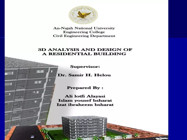
Abstract. This project is a structural analysis and design of a residential building located in JENIEN City, The building is consisted of 7 floors.

E N D
Abstract This project is a structural analysis and design of a residential building located in JENIEN City, The building is consisted of 7 floors. The final analysis and design of building is done using a three dimensional (3D) structural model by the structural analysis and design software sap2000.
The preliminary dimensions of the structural elements are determined using one dimensional structural analysis for the structural members for gravity loads. Contain analysis and design is used for this purpose. The structural model results are verified by simple calculations and by comparing with the one dimensional analysis.
Contents CHAPTER ONE: (Introduction) * Description of project * Materials * Loads * Design Code
CHAPTER TWO:(PRELIMINARY DESIGN ) * General * Design of Rib Slab * Design of columns * Design of beams
CHAPTER THREE: (Three Dimensional Analysis And Design) * General * Modeling The Building as 3D * Seismic Loads * Analysis and Design of Slabs * Analysis and Design of Beams * Analysis and Design of columns * Analysis and Design of Footings * Analysis and Design of Stair *Analysis and Design of walls
**CHAPTER ONE: INTRODUCTION *General: This project introduces analysis and design of reinforce concrete residential building. Also this project provides clear design structural drawings for construction. This project is a residential building , which consists of 7 stories above the ground level . The area of each story is about 372 m².
*Materials Concrete strength f'c=300Kg/cm² Modulus of elasticity equals 261534 Kg/cm² Unit weight is 2.5 ton/m3. Fy= 4200 kg/cm2 (420 Mpa)
*Loads: -Live Load= 0.25 t/m² -Superimposed dead load=0.27 t/m² - Additional dead load=0.1 t/m²
*codes and standard: 1- ACI 318-08 (AMERICAN CONCRETE INSTITUTE) 2- UBC-97:(UNIFORM BUILDING CODE)
**CHAPTER TWO: PRELIMINARY DESIGN -Soil capacity = 2.8 kg/cm² -Concrete strength f'c=300Kg/cm² -Steel yield strength, Fy= 4200 kg/cm2 *General:
*Design of Rib Slab: -Minimum slab thickness is calculated according to ACI 318-08 provision. ACI 318-08
One end continuous = L / 18.5 = 425/18.5 =23 cm Cantilever = L/8=160/8=20 cm Then we assume thickness of slab (h) rib= 25 cm Cross section in Ribbed slab
The distribution of ribs in the typical slabs shown in figure
The ribs in the slab are analyzed using sap2000 program. As an example, the analysis result of rib are illustrated here: Use 2φ12 top and 2φ10 bottom steel moment diagram for rib, ton.m
*Design of columns In this project rectangular columns are used. And these columns can carry axial load and no moment. -Design of Column : The dimensions of the column 30*35cm, Ag=1050cm², And we use ρ between (1%- 4%) Pu=149 ton Pn=229 ton As =11 cm² Use 6 φ16
*Design of beams After distributed the beam in the plan as shown in figure , we insert to sap2000 and insert each load on it which come from ribs slab or from external or internal wall and then design it.
-Design of beam (65*25): moment diagram, ton.m Area of steel , cm² Use 8φ18 top and 5φ18 bottom steel
**CHAPTER THREE: Three Dimensional Analysis And Design *General: This chapter provides analysis and design of 3D model for the building using sap2000 program. Figure belowshow 3D Model of it. 3D model
*Modeling The Building as 3D Structure : **Sections: -shear walls= 20cm -Ribbed slabs are presented as one way solid slabs in y-direction. The thickness is calculated to be equivalent to ribs moment of inertia. Z = (12*17*17*.5*52*8*21)/((12*17)+(52*8)) Z=16.9 cm Ic = (52*8^3)/ 12 +(52*8*4.1^2) + 12*17*8.4^2 Ic= 28.518.9 cm^4 52*(Equivalent)^3/ 12 =28518.9 H=18.74cm
-beams: Variable in sections, we use concrete covers of 3 cm Moment of inertia about 2 axis = Moment of inertia about 3 axis=0.35 -columns : we use concrete covers of 4 cm Moment of inertia about 2 axis = Moment of inertia about 3 axis=0.7 **Loads: -Own weight : willbe calculated by the program. -Live load= 0.25 ton/m2. - Total super imposed dead load =0.37ton/m2
-seismic loads First we will define the equivalent static As shown in the picture
we define the cases of the seismic loads Seismic-x, Seismic-y
*Structural Model Verification: Equilibrium Check: -Live Load: Total Live load =6833.8 KN Live load from SAP =6785 .2 KN % Error =0.8% < 5% ok
-Dead loads: Total load=31791.2 KN Dead load from SAP =32216.6 KN Error= 1.5% < 5% ok.
super imposed Dead load:total S.D = 9870 KNFrom Sap = 9622.7 KN Error= 2% < 5% ok
*Analysis and Design of Slabs : -check shear :
*Analysis and Design of Beams: Analysis and design output was taken from SAP2000.
*Analysis and Design of columns : Analysis and design output was taken from SAP2000. Design the worst column (has the max. axial load = 212 Ton) Assume column dimension: 30cm *60cm Pd=φλ*0.85(300(Ag-As)+ 4200*As) = 0.65 *0.8 *0.85 (300(0.99*30*60)-(4200*0.01*30*60)) =275.6 ton > 212 ok As = 0.01 *30*60 = 18cm2 → Use 8φ18 mm
*Analysis and Design of Footings : • -Single Footings Footing (F4) : Pu= 212 t, Ps = 166 t Footing Area (A) = Ps./B.C.= 166/28 = 5.9 m² Footing dimensions : 2*3m Ultimate pressure (qu) = 212 /6 = 35.3 t/m² Wide beam shear : Vu = 35.3 ton ФVc > Vu ok ФVc=39.4 ton, Check Punching shear : ФVc > Vu ok ФVc=248.6 ton, Vu=185.7 ton Flexural design: Mu = qu*L²/2= 25.4ton.m/m As=16 cm²/m Use 8Ф16/m bottom steel in both directions
-Wall Footings Same steps of single footing
-Elevator Footings Pu= 905 t, Ps = 710 t Footing Area (A) = Ps./B.C.= 25.4m² Footing dimensions : 5*5.5=27.5m² Ultimate pressure (qu) = 905 /27.5 = 32.3 t/m2 Wide beam shear 1: (simply supported) ФVc=33 ton, Vu = 29.4 ton ФVc > Vu ok Wide beam shear 2: (cantilever) ФVc=33 ton, Vu = 17.2 ton ФVc > Vu ok .
Flexural design: • M1: • Max negative moment from sap= 21.4 t.m • Mn =23.7 • As= 15cm² • Use 8φ16 • Max. positive moment = 8 t.m • Mn= 9 t.m • As=8 cm² • Use 5φ16
Maximum ( –ve)and (+ve)moments = 0.52Ton .m/m Maximum ( –ve)and (+ve)moments = 0.52Ton .m/m Maximum ( –ve)and (+ve)moments = 0.52Ton .m/m • *Analysis and Design of Stair : - going of the stair is 30cm as standards - Flights and landings thickness will be taken as simply supported solid slab: height of landing=ln/20=270/20=13.5 cm. 15 cm thickness is suitable. Rise of stair= 16cm, -Design of the stair from sap M11: Maximum ( –ve )and (+ve )moments = 0.52Ton .m/m =0.0009< 0.0018 As =0.003 *100 *12 = 3.7 /m →use 3φ14 top and bottom steel is required
Maximum (–ve) and (+ve) moment is 1.8 Ton.m/m. • Maximum (–ve) and (+ve) moment is 1.8 Ton.m/m. • =0.003<< 0.0018 • As =0.003 *100 *12 = 3.7 /m →use 3φ14 top and • bottom steel is required