Download
1 / 49
510 likes | 678 Views
Aerospace Systems Engineering as an Integrating Function for the Georgia Tech Graduate Program in Aerospace Systems Design. Dr. Daniel P. Schrage Professor and Director Center of Excellence in Rotorcraft Technology (CERT) Center for Aerospace Systems Analysis (CASA). Presentation Outline.

E N D
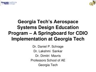
Aerospace Systems Engineeringas an Integrating Functionfor the Georgia Tech Graduate Program in Aerospace Systems Design Dr. Daniel P. Schrage Professor and Director Center of Excellence in Rotorcraft Technology (CERT) Center for Aerospace Systems Analysis (CASA)
Presentation Outline • Overview of the Graduate Program Aerospace Systems Design Program • The Evolution from an IPPD to an IPPD through RDS to a Modern Aerospace Systems Engineering Approach • Description of the Graduate Course in Aerospace Systems Engineering • Opportunities for Collaboration with the School of ISYE
Georgia Tech School of AE • School of Aerospace Engineering • One of original six Guggenheim Schools of Aeronautics • 34 full time faculty • ~600-700 undergraduate students (AE majors) • ~250 -300 graduate students • Highest Rated Public Aerospace School (Overall: UG – 2nd to MIT;GR-3rd to MIT & Stanford, U.S. News & World Report) • Six Disciplinary Groups (Full A.E. School) • Aerodynamics and Fluid Mechanics • Structural Mechanics and Materials • Propulsion and Combustion • Flight Mechanics and Controls • Structural Dynamics and Aeroelasticity • System Design and Optimization
Includes core and elective courses to: Provide a Practice-oriented M.S. Program Provide a Integrated-Discovery Focused Ph.D program Includes a combination of disciplinary, methods and synthesis courses for System Design of Complex Systems: Aircraft and Rotorcraft Missiles and Space System of Systems: Army/DARPA FCS; FAA/NASA NAS Integrates Research and Education Two active research laboratories, ASDL and SSDL Approx. 100 students (~80 supported) Approx. 15 research engineers Uses an IPPD through RDS Approach and a modern Aerospace Systems Engineering Course as an Integrating Function for the Program Graduate Program in Aerospace Systems Design
Graduate Program Development ‘84 - Graduate Rotorcraft Design Program Established ‘89 - Intro to Concurrent Engineering (CE) & Design for LCC courses ‘92 - Graduate, CE/IPPD Fixed-Wing Design Program Established w/ NASA’s USRA ‘94- NASA MDA Fellowship Grant and New Approaches to MDO Grant ‘95-’96 Space Systems Design Laboratory (SSDL) Established ‘97- NRTC Center of Excellence Renewal ‘98- Center for Aerospace Systems Analysis (CASA) Initiated ‘99- Boeing Awards GTAE/CASA Faculty Chair in Aerospace Systems Analysis ’00 GEAE USA ‘94 CE/IPPD Focus: Affordable Aerospace Systems Design Methodology; ASDL Estab. ‘95 RSM for Advanced Synthesis Focus: Pioneering Research into Response Surface Methodology (RSM) for advanced sizing/synthesis Focus: Addressing Economic Uncertainty & Viability results in Robust Design Simulation ‘96 RDS Aero + Structures Focus: Efficient Probabilistic Analysis through Fast Probability Integration (FPI) ‘97 FPI Probabilistic Feasibility AND Viability ‘98 • Morphological Matrices • Pugh Diagram CASA FLOPS-IMAGE-RSE Interface developed y2 Focus: Systems & System of Systems Analysis for Complex Systems and Movement toward a Modern Approach to Systems Engineering y1 yn FPI Customer Requirements Feasible Solution $/RPM Probability Sizing Desired Solution Econ. Establish the Need $/RPM Target Baseline Mean x1 xn x2 Evolution of the Georgia Tech Aerospace Systems Design Program
Is the Only Formal Graduate Aerospace Systems Design Program in the U.S., and probably throughout the world Addresses the System Design of Complex Systems (Not Conceptual Design) utilizing a Generic IPPD Methodology, as a modern approach for Systems Engineering Provides an engineering approach to Risk Based Management through Robust Design Simulation (RDS) environment for Implementing the IPPD Methodology at the “Front End” that can be continued for Process Improvement and Merging with Six Sigma methods Provides a practical way of incorporating “lean” and other initiatives into the front end of a complex system’s life cycle Has spun off various methods, tools, and techniques from this IPPD through RDS approach for a variety of customers Have moved to address “System of Systems” problems such as FCS and air transportation architectures for the NAS Why it is Unique?
School of A.E.:Primary Faculty Dr. Dimitri Mavris, Director of ASDL and Boeing Chair Professor in Advanced Aerospace Systems Analysis Dr. John Olds, Associate Professor and Director of SSDL Dr. Jim Craig, Professor and Co-Director of CASA Dr. Dan Schrage, Professor and Director, CASA & CERT Two recruitments: Lewis Chair in Space Systems Technologies; Junior Faculty in Design Methodology & Tools Supporting Faculty: Dr. Amy Pritchett (AE/ISYE), Dr. Eric Johnson, & Dr. JVR Prasad Some Participation from the School of M.E. Dr. Farokh Mistree, Professor and Director of SRL Dr. Bob Fulton, Professor Some Participation from the School of E.C.E Dr. George Vachtsevanous, Professor and Director of the Intelligent Control Laboratory Who are the Primary & Supporting Faculty?
Established in1998 based on successful development of the ASDL from 1992 and the successful development of the SSDL from 1995; Serves as oversight for these labs Through its laboratories provides the primary research support to the graduate program in Aerospace Systems Design which currently has ~ 100 students of which over 80 % are U.S. citizens Research support provides over $5M per year in sponsored research and supports ~ 80 students & 15 research engineers Provides a modern approach to systems engineering based on an Integrated Product/Process Development (IPPD) methodology executed through Robust Design Simulation(RDS) Overview of Center for Aerospace Systems Analysis (CASA)
Why Systems Analysis? • Systems Analysis is a scientific process, or methodology, which can best be described in terms of its salient problem-related elements. The process involves: • Systematic examination and comparison of those alternative actions which are related to the accomplishment of desired objectives • Comparison of alternatives on the basis of the costs and the benefits associated with each alternative • Explicit consideration of risk • NASA, DoD, and Industry are realizing that more emphasis must be placing on enhancing systems analysis at the front end of the life cycle using modern systems engineering approaches
CASA’s Laboratories Space Systems Design Lab www.ssdl.gatech.edu Aerospace Systems Design Lab www.asdl.gatech.edu Flight Sim Lab B.S.A.E. - M.S. - Ph.D Degrees Design, Build, Fly Lab Design Frameworks Lab Uninhabited Aerial Vehicle Research Facility IPERT Lab
An Integration and Practice-Oriented M.S.Program in Aerospace Systems Design Semester I Semester II Summer ISE/PLMC Development Design Methods/Techniques Aerospace Propulsion Disciplinary Systems Electives Systems Engineering Design Special Project Applied Applied Systems Systems Design I Design II Design I Design II Safety By Design Modern Modern Product Design Design Life Cycle Methods I Methods II Management Internship Design Tools/Infrastructure Mathematics (2 Required) Other Electives Legend: Core Classes Elective Classes
Aerospace Systems Design Laboratory Classroom Implementation Aerospace Systems Design Education & Research Philosophy Industry Government Relevant Problems Partners: GEAE RRA LMTAS Boeing Sikorsky Partners: ONR NASA AFRL NRTC • Methods Formulation • Supports Basic Research • Implementation of Methods Data & Tools Funding Funding Methods Students
A paradigm shiftis underway that attempts to change the way complex systems are being designed Emphasis has shifted from design for performance to design for affordability, where affordability is defined as the ratio of system effectiveness to system cost +profit System Cost - Performance Tradeoffs must be accommodated early Downstream knowledge must be brought back to the early phases of design for system level tradeoffs The design Freedom curve must be kept open until knowledgeable tradeoffs can be made Design Process Paradigm Shift(Research Opportunities in Engineering Design, NSF Strategic Planning Workshop Final Report, April 1996)
Integrated Product/Process Development (IPPD) is a management methodology that incorporates a systematic approach to the early integration and concurrent application of all the disciplines that play a part throughout a system’s life cycle (Technology for Affordability: A Report on the Activities of the Working Groups to the Industry Affordability Executive Committee, The National Center for Advanced Technologies (NCAT), January 1994) IPPD evolved out of the commercial sector’s assessment of what it took to be world class competitive in the 1980s The DoD has required IPPD and the use of IPTs where practical throughout the DoD Acquisition Process for Major Systems (DoD 5000.2R) Conduct of IPPD requires Product/Process Simulation using Probabilistic Approaches What is IPPD?
Cost Advantage Cheap Labor Hi Volume, Lo Mix Production Quality Statistical Process Control Variability reduction Customer Satisfaction Time-to-Market Cycle time Comparison (JIT) Integrated Product/Process Development Product/Process Simulation Hi Skill adaptable Workforce Manufacturing Enterprise Flexibility Product Variety Cost Independent of Volume Agility Commercial/Military Integration Virtual Companies Company Goodness Environment 1960 1970 1980 1990 2000 Quality Revolution - Where Competition is Today NCAT Report, 1994
Japanese Auto Industry Made Changes Earlier Than U.S. Auto Industry
Traditional Design & Development Using only a Top Down Decomposition Systems Engineering Process
CONCEPTUAL DESIGN (SYSTEM) SYSTEM SYSTEM PROCESS FUNCTIONAL RECOMPOSITION DECOMPOSITION Product Process Trades Trades PRELIMINARY PRELIMINARY DESIGN DESIGN (PARAMETER) (PARAMETER) INTEGRATED PRODUCT COMPONENT COMPONENT Process Product PROCESS FUNCTIONAL PROCESS Trades Trades RECOMPOSITION DECOMPOSITION DEVELOPMENT DETAIL DETAIL DESIGN DESIGN (TOLERANCE) (TOLERANCE) Process Product Trades Trades PART PART PROCESS FUNCTIONAL RECOMPOSITION DECOMPOSITION MANUFACTURING PROCESSES IPPD Requires the Computer Integration of Product and Process Models and Tools for System Level Design Trades and Cycle Time Reduction
MULTI-LEVEL LCC MODEL Process Recomposition ENGINEERING MODELS Product Decomposition re-design decision Top-Down Aircraft LCC Model Aircraft Synthesis (Sizing) cust. requirements cost model cost metrics performance metrics perf. requirements req’d inputs wing planform geometry Integrated Design Environment bottom-up wing cost estimate Finite Element Analysis labor rates Component Cost Modeling materials product metrics process metrics learning curves loads weights labor hours material costs KBS Process Modeling structural concepts alternative processes Integrated Product and Process Development Modeling Flow (Aircraft Example)
• Representative structure at each location – upper and lower panels – rib and spar structure Aft wing box – variable chordwise load intensities due to wing bending – high spanwise load intensities Wing tip box – stiffness critical due to aeroelastic effects – high load intensities Forward wing box – low load intensities with respect to wing bending – minimum gage region HSCT Integrated Design & Manufacturing Ph.D Thesis (W. Marx, 1997) Wing Point Design Regions William J. Marx
AIRLINE PAYMENT SCHEDULE PRODUCTION SCHEDULE AIRCRAFT WEIGHTS ENGINE RDT & E THRUST & WGHT. COSTS LABOR MANUFACTURER AIRCRAFT MANUFACTURER CALCULATE YES ROI PRICE RATES UNIT VS MANUFACTURER MANUFACTURING CASH-FLOW COSTS CASH-FLOW PRODUCTION COSTS ROI QUANTITY AVERAGE LEARNING COST CURVES NO AIRCRAFT MISSION P r o d u c t i o n A i r l i n e PERFORMANCE Y i e l d Q u a n t i t y FUEL, INSURANCE AIRLINE R O I DEPRECIATION RATES OPERATING LABOR & BURDEN COST RATES P R I C E TAX RATE COSTS INDIRECT DIRECT REVENUE COSTS AIRLINE AIRLINE YES CALCULATE ROI PRICE RETURN ON VS AIRLINE ROI INVESTMENT NO ACQUISITION PREPAYMENT TOTAL SCHEDULE & DEPR. SCHEDS OPERATING COST Aircraft Life Cycle Cost Analysis (ALCCA) - including Economic Analysis
Previous Mfg Cost Module Component Weights Engine Thrust and Weight Labor Rates Production Quantity Learning Curves Aircraft Manufacturing Costs Component Costs Unit Costs RDT&E Costs Avg. Costs Manufacturing Hours Quality Assurance Hours Tooling Hours (Raw Material Costs) (Buy-To-Fly Ratios) Material Costs Material Breakdown Mfg. Labor Rate Qual.Assur. Labor Rate Material Burden Rates Mfg. Labor L. Curve QA Labor L. Curve Tooling L. Curve Material L. Curve from CLIPS New ALCCA output New Wing Production Module Aircraft Manufacturing Costs Wing TFUC Manufacturing Hours & Cost Quality Assur. Hours & Cost Tooling Hours & Cost Material Costs Cost/Time Analysis new ALCCA input Wing Production PBC Module Theoretical First Unit Cost Component Weights Engine Thrust Component Costs Unit Costs Non-Recurring & Recurring Production Labor Rates Production Quantity Learning Curves RDT&E Costs Average Unit Costs Aircraft Process Based Manufacturing Cost Model
Cumul. time Cost/Time Curve End Points for Wide Range of Projected Lot Sizes Finishing Operations Largest Run Production Theoretical First Unit Cost (TFUC) Setup Smallest Run Design Tools Cost / Unit Purchase Material Material Cost Setup Cost Tool Design Cost Finishing Operations Cost Smallest Run Production Cost Largest Run Finishing Operations Cost Largest Run [Source: MIL-HDBK-727] Production Cost Smallest Run Cost Time Analysis for Theoretical Production
Cost/Time Curve Process A End Point Process E Process B End Point Process C End Point TIME Process D End Point UNIT COST Cost/Time Constraint Curve for Candidate Selection [Ref. MIL-HDBK-727]
Probabilistic Cost/Time Production Analysis Cumul. time Cost/Time Curve End Points for Wide Range of Projected Lot Sizes Finishing Operations Largest Run Production Theoretical First Unit Cost (TFUC) Setup Smallest Run Design Tools Cost / Unit Purchase Material Material Cost Setup Cost Tool Design Cost Finishing Operations Cost Smallest Run Production Cost Largest Run Finishing Operations Cost Largest Run Production Cost Smallest Run [Ref. MIL-HDBK-727]
Methodology provides a procedural design (trade-off iteration) approach based on four key elements: Systems Engineering Methods and Tools(Product design driven, deterministic, decomposition approaches; MDO is usually based on analytic design approach) Quality Engineering Methods and Tools(Process design driven, nondeterministic, recomposition approaches; MDO is usually based on experimental design approach) Top Down Design Decision Process Flow (Provides the design trade-off process) Computer Integrated Design Environment(Information Technology driven) Methodology has been implemented through Robust Design Simulation (RDS) for a number of applications Georgia Tech Generic IPPD Methodology
The Systems Engineering Process • Process Input • Customer Needs/Objectives/ Requirements • - Missions • - Measures of Effectiveness • - Environments • - Constraints • Technology Base • Output Requirements from Prior Development Effort • Program Decision Requirements • Requirements Applied Through • Specifications and Standards System Analysis & Control (Balance) • Requirements Analysis • Analyze Missions & Environments • Identify Functional Requirements • Define/Refine Performance & Design • Constraint Requirement • Trade-Off Studies • Effectiveness Analysis • Risk Management • Configuration Management • Interface Management • Performance Measurement • - SEMS • - TPM • - Technical Reviews Requirement Loop • Functional Analysis/Allocation • Decompose to Lower-Level Functions • Allocate Performance & Other Limiting Requirements to • All Functional Levels • Define/Refine Functional Interfaces (Internal/External) • Define/Refine/Integrate Functional Architecture Design Loop • Synthesis • Transform Architectures (Functional to Physical) • Define Alternative System Concepts, Configuration • Items & System Elements • Select Preferred Product & Process Solutions • Define/Refine Physical Interfaces (Internal/External) Verification Related Terms: Customer = Organization responsible for Primary Functions Primary Functions = Development, Production/Construction, Verification, Deployment, Operations, Support Training, Disposal Systems Elements = Hardware, Software, Personnel, Facilities, Data, Material, Services, Techniques • Process Output • Development Level Dependant • - Decision Data Base • - System/Configuration Item • Architecture • - Specification & Baseline
Geometry Mission Modeling and Simulation:Varying Fidelity of Synthesis and Sizing Safety Safety Economics Aerodynamics Aerodynamics Economics S ynthesis & Sizing S&C Manufacturing Manufacturing S&C Integrated Routines Table Lookup Increasing Sophistication and Structures Complexity Performance Conceptual Design Tools ( First-Order Methods) Approximating Functions Direct Coupling of Analyses Propulsion Structures Performance Preliminary Design Tools ( Higher-Order Methods) Propulsion
The Quality Engineering Process provides Recomposition Methods & Tools Knowledge Feedback Seven Management and Planing Tools Off-Line Quality Function Deployment Off-Line Robust Design Methods (Taguchi, Six - Sigma, DOE) Off-Line Statistical Process Control On-Line Customer • Identify Important Items • Variation Experiments • Make Improvements • Hold Gains • Continuous Improvement • Needs Having heard the “voice of the customer”, QFD prioritizes where improvements are needed; Taguchi provides the mechanism for identifying these improvements
CoVE: Collaborative Visualization Environment for Complex Systems Design Funded by the Defense University Research Instrumentation Program (DURIP) February 2003
CoVE Objectives • A semi-immersive, very high resolution, Collaborative Visualization Environment (CoVE). • Used to investigate the use of semi-immersive virtual environments in collaborative design processes. • Basic concept for the CoVE is a large, high resolution display wall similar to those developed for media companies and operations centers. • It will allow us to apply emerging probabilistic design methods to problems at an industrial scale. • It is expected to promote new research in design, visualization and usability with other leading centers on campus.
CoVE Features • A single CoVE with a 25 M-pixel resolution curved data wall measuring 20 ft wide by 12 ft tall. • Seating for up to 12 participants, each with their own computers and local displays. • The basic design will be configured so that it can be used with another CoVE to execute distributed collaborative design with another team at a remote location. • The CoVE will include both single person and group video conferencing capabilities. • Project budget: $630k
Example ASDL Application Unified Trade-off Environment Morphological Matrix QFD Mission Profile Constraint Analysis Video Conference Technology Impact Matrix RAM Model Technology Profiles JPDM CDF CFD Visualization
Weber 2nd Floor Site Operations Video Conferencing Observers Data Wall Participants
CoVE Tentative Schedule • Award announcement:February 2003 • Final specifications:April 2003 • Site preparations:May 2003 • Construction & Installation:July 2003 • Testing:September 2003 • Acceptance:October 2003
Aerospace Systems Engineering Course: AE 6370 • Introduces new graduate students to Aerospace Systems Engineering and a methodology for Implementing it through IPPD through Robust Design Simulation (RDS) • Consists of covering traditional systems engineering methods and tools; introduces quality engineering methods and tools; introduces multi-attribute decision methods; and introduces the need for a computer integrated environment • Course consists of a mid-term exam and team projects (~5 students per team) addressing the concept formulation for complex systems or system of systems • Utilizes a simple set of integrated tools to allow the teams to conduct the first iteration through a complex system design • Will be offered as a distance learning course for the first time in Fall 2003
Aerospace Systems Engineering Taught using an Integrated Set of Tools
Ten Complex System Formulation Projects from AE6370, Fall 2002 • AIAA Graduate Student Missile Design Competition: “Future Target Delivery System(Missile Multipurpose Target” • RFP for a “High Firepower Payload for Missile Defense (Missile Interceptor) • NASA Sponsored University Competition for the “Conceptual Design of a Titan (Saturn’s largest moon) Vertical Lift Aerial Vehicle” • AHS/NASA Student Design Competition for “VTOL Urban Disaster Response Vehicle” • NASA “Personal Air Vehicle Evaluation Program: to identify VTOL and ESTOL Concepts” • RFP for a “Quiet Supersonic Business Jet” in conjunction with Gulfstream Aerospace Company • DoD Potential Joint Program for an “Air Maneuver & Transport Concepts for the Objective Force” • AIAA Student Competition for “Subsonic Commercial QuEST” • AUVS International Aerial Robotics Competition and DARPA Project: “Intelligent Uninhabited Aerial Vehicle (UAV) using Software Enabled Control (SEC)” • Army Aviation Recapitalization Program: “Technology and Risk Assessment for the Army’s UH-60M Helicopter Improvement Program”
Integrated Product/Process Development (IPPD) means applying Concurrent Engineering at the front end of a system’s life cycle where design freedom can be leveraged and product/process design tradeoffs conducted in parallel at the system, component, and part levels Implementation of IPPD requires moving from a deterministic point design approach to a probabilistic family design approach to keep the design space open and from committing life cycle cost before the system life cycle design trade-offs can be made Robust Design Simulation (RDS) provides the necessary simulation and modeling environment for executing IPPD at the System level Continuation of RDS along the system life cycle implies the creation of a Virtual Stochastic Life Cycle Design Environment An Overall Evaluation Criterion (OEC) based on System Affordability should be identified early and its variability tracked along the life cycle time line What is IPPD Through RDS
Roadmap to Affordability Through RDS Robust Design Simulation Subject to Robust Solutions Design & Environmental Constraints Technology Infusion Physics-Based Modeling Activity and Process-Based Modeling Objectives: Schedule Budget Reduce LCC Increase Affordability Increase Reliability . . . . . Economic Life-Cycle Analysis Synthesis & Sizing Operational Environment Simulation Impact of New Technologies-Performance & Schedule Risk Economic & Discipline Uncertainties Customer Satisfaction
FPI / MC Interactive RDS Environment
CONCEPT VALIDATION FULL SCALE DEVELOPMENT PRODUCTION DEVELOPMENT Risk & Uncertainty are Greatest at the Front KNOWNS KNOWN-UNKNOWNS UNKNOWN-UNKNOWNS
Coninuous RDS along the System Life Cycle to link the “fuzzy front end” to the “process capability approaches” Bring the Development Process Approach Six-Sigma, Under Control, C = 1 Define Distributions 1 < C < 2 p p Six-Sigma Achieved, C = 2 p Continuous Product Improvement / Innovation Uncertainty Risk Management/Reduction Overall Fuzzy Front End Evaluation Criterion Upper Specification (OEC) Response OEC Target Lower Specification System Definition System Integration Manufacturing System Design & (Detail/Tolerance) (On-Line Quality) (Preliminary/Parameter) Tech. Development (Conceptual/System) Traditional C and C Approach for Continuous, On-line Process Improvement p p k Overall Upper Specification Evaluation Criterion (OEC) Response OEC Target Lower Specification Initial Distribution Reduced Variability and Improved Mean Response Time
The VSLCDE- Key Characteristics The purpose of VSLCDE is to facilitate design decision- making over time (at any level of the organization) in the presence of uncertainty, allowing affordable solutions to be reached with adequate confidence. It is a research testbed. • Virtual . . . Simulation-based system life-cycle prediction • Stochastic . . . Time-varying uncertainty is modeled; temporal decision-making • Life-Cycle . . . the design, engineering development, test, manufacture, flight test, operational simulation, sustainment, and retirement of a system. The operational simulation includes virtual testing, evaluation, certification, and fielding of a vehicle in the existing infrastructure, and tracking of its impact on the economy, market demands, environment. • Design . . . Implies that the environment’s main role is to provide knowledge for use by decision-makers, especially for finding robust solutions • Environment . . . Implies the support of geographically distributed analyses and people through collaboration tools and data management techniques
Some Opportunities for Collaboration between the Schools of AE and ISYE • Integration of ISYE Logistics with AE Aerospace Systems Design Program for a variety of customers (Industry and Government) • With Lockheed Martin on a Modern Systems Engineering Approach (addressing Product Life Cycle tradeoffs from the Outset) based on the Joint Strike Fighter (JSF) Development Approach successes and Lessons Learned (POC: Bill Kessler, LM Lean Enterprise Mgr and Tom Burbage, LM JSF VP) • With OSD/DOD/USAF New Focus on Systems Engineering Education and Research • With USAF – GT(CEE) Initiative in taking over the Lean Sustainment Initiative from MIT • With NASA Langley National Institute of Aerospace (NIA) and with NASA Ames Engineering of Complex Systems (ECS) programs • Others?