Download
1 / 72
730 likes | 1.11k Views
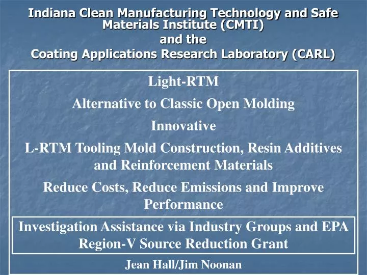
Light-RTM Alternative to Classic Open Molding Innovative L-RTM Tooling Mold Construction, Resin Additives and Reinforcement Materials Reduce Costs, Reduce Emissions and Improve Performance Investigation Assistance via Industry Groups and EPA Region-V Source Reduction Grant

E N D
Light-RTM Alternative to Classic Open Molding Innovative L-RTM Tooling Mold Construction, Resin Additives and Reinforcement Materials Reduce Costs, Reduce Emissions and Improve Performance Investigation Assistance via Industry Groups and EPA Region-V Source Reduction Grant Jean Hall/Jim Noonan Indiana Clean Manufacturing Technology and Safe Materials Institute (CMTI) and the Coating Applications Research Laboratory (CARL)
Light-Resin Transfer Molding Project From This: To This:
Emissions-Related Cost Example L-RTM product manufacture eliminates resin chop emissions and thus eliminates resin spray booth exhaust fan/make-up air heat losses
FRP Companies Supplying Materials/Services • Partnering FRP manufacturers: Elkhart, IN area • Airtech International • American Composites Manufacturers Association • Ashland Chemical • Composites One • Cook Composites and Polymers • Dow Chemical • Freeman Wax Company • Glas-Craft • Interplastic Corporation • JHM Technologies • John Guest Company • Magnum Venus Products • Nida-Core • RTM North • Saint-Gobain/Vetrotex
Light-Resin Transfer Molding Project (L-RTM) Continuing technical assistance to the State’s $6 billon industry L-RTM Represents Emission Reduction Potentials of Greater than 85% CARL lab is researching an innovative alternative to the classic open mold method of FRP production – L-RTM. The project is investigating vacuum infusion and pressure assisted transfer of resin material into light mold tooling as an alternate method to open mold fabrication. Master Mold for RV Rear Cap Indiana Built “Class A” RV
First example
Application of sheet wax to make annular space thickness equal to the part for RTM resin to flow into.
Application of all layers of sheet wax is complete and red and black stripping to form the seal channels is in place.
Placement of vacuum ports and resin injection ports. The original female tool mold is under the sheet wax.
Application of black tooling gel coat over several coats of PVA previously applied to the sheet wax surface. The PVA acts as a release agent to separate the wax from the gel coated tool-contra-mold ( tool mold for B side).
Complete build-up of over 7 layers of glass mat and tooling resin as well as balsa and steel reinforcement, all over the sheet wax (and original female mold) which is still underneath.
Newly constructed male tool mold (Contra-mold), turned upside down. Female tool-mold Original female mold now separated from the contra-mold that was constructed over top of it. Note that the sheet wax (95%) transferred to the contra-mold.
Catch pot for resin overflow from cavity (cavity vacuum set at -15 in. Hg) Contra-mold placed over the female mold and ready for resin injection Resin injection tube Flange vacuum (-25 in. Hg) Holds contra-mold to female mold 2 Venturi vacuums; 1 for vacuum flange and 1 for product cavity vacuum Motor Cover produced via moldabove Smooth surfaces, top and bottom, without gel coat
Note: Smooth surface, no sharp glass shards or fibers, safer handling, consistent dimensions, accurate accounting of raw material usage, better component fit, etc.. Significantly stronger part than open-mold equivalent. 24% lighter than open-mold equivalent. Essentially 0 emission
Another example
Continued CARL Construction of Closed-Mold Tool -- A Marine Hatch Cover
Hatch Cover Key Statistics – example of an L-RTM Part: • 36% glass to 25% glass depending on loading • 4.5 minute infusion time (vacuum assisted only) • 50-60 minute cure time, should optimize down to • 40 min. • The L-RTM part is estimated to cut labor time by over • 50% vs. the open molded equivalent. • L-RTM hatch (cut in half) supports over 350 lbs. • estimated to be nearly twice as strong as the • open molded equivalent. • Thickness variation – 11 thousands of an inch • (excellent tolerance –impossible with the • open molding process) • Achieves at least an 85% reduction in emissions of • styrene to the environment
Novel Use of Vacuum Reducing Costs and Labor
Fine veil cut to ¼ inch wide strips. The strips when hooked to a vacuum source convey vacuum throughout the mold cavity so that two layers of wax are not needed: Significant reduction in tooling mold construction costs due to: 1) 40 mil sheet wax is no longer required for vacuum; 2) labor reduction because exact compound angle cuts on the 40 mil wax is negated. Veil under the wax
Construction of L-RTM Contra-Tooling Mold for Tonneau Cover “B” side of recently separated Contra-Mold – all sheet wax must be removed and the mold must be “prepped” and cleaned This side of the wax was held down against the surface of the orange mold by the vacuum veil strips – no “second layer” 40 mil vacuum wax was used – significant cost savings
Infusion of Tonneau Cover Note wave front of infused resin
Deflection Indicator Weight Platform Force Application Point Test Bar Tonneau-Section Deflection Check Supports
Tonneau Cover Deflection Comparison 99 mils thick Wt. = 29 lbs 93 mils thick Wt. = 29 lbs Light Blue L-RTM 165 mils thick Wt. = 31 lbs Thickness with little weight increase due to microspheres 146 mils thick Open mold Wt.= 60 lbs Dark blue line is open mold flex strength which is equaled by the 165 mil thick L-RTM part, yet the thick L-RTM part is still half the weight of the 146 mil thick open molded part. The addition of microspheres added bulk thickness/stiffness yet reduced weight so part is thick and stiff yet light and economical.
Over 30,000 Lbs. force is applied to the part-section of this mold. If vacuum is drawn without glass, etc. having been loaded in the cavity, the two mold halves are readily pulled together until massive contact of the two halves is made. When glass has been loaded into the cavity and vacuum is drawn, the glass will be squeezed to its maximum compaction. In other words, the cavity thickness changes and the fill rate can be hampered. Both the primary female mold and the contra mold, flex significantly. Addition of steel reinforcing bars to the primary mold restricts its flexure but the difference just shifts to become added flex of the contra. A positive stop along the side of the mushroom seal is recommended because of the fulcrum effects and over-compression of the seal that results without it. Even so, this does not completely eliminate the mold-flex/cavity-closure effect. Which ever port (vacuum or resin feed line) is shut off when fill is completed, and the vacuum level maintained after cavity fill, can affect the finished part thickness.
Innovation Production of a Contra-mold using Vacuum Infusion
Innovation Use of 30 mil flexible, yet tough polyethylene tape (25 mils PE/5 mils adhesive) Use of 20 mil flexible, yet tough polyethylene tape (15 mils PE/5 mils adhesive) – Protects the sheet wax from vacuum infusion rigors Traditional sheet wax 110 mil Use of 30 mil tough polyethylene tape (25 mils PE/5 mils adhesive) This material will not deform under the mushroom seal channel profile rib pressure (vacuum induced)
Contra-mold producing wax lay-up, covered in protective polyethylene (PE) layer, is now ready to resist the rigors of pressure/compression of vacuum infusion and heat of resin cure. The PE layer shields the wax and prevents it from the deforming pressures of infusion. CMTI/CARL Lab Innovations Tradition Sheet Wax
Wax/PE covered mold from previous slide is under Saint-Gobain RTM glass Saint-Gobain RTM Glass effectively conforming to the shape of the mold Resin delivery spiral-wrap Flow enhancing mesh Peel ply
Checking resin flow rate through highly compressed glass Confirming Flow Rate for Proper Gel Time Adjustment for Actual Infusion of Full Size Contra-Mold
Glass-mat, peel ply, flow mesh, spiral wrap applied Application and sealing of plastic vacuum film over mold assembly Drawing vacuum after attaching resin-supply and vacuum lines Infusion of tooling resin and forming of contra-mold
InfusedContra-Mold Removal PE covered wax intact and undamaged during removal of contra-mold – proof of concept – more than one contra-tooling mold may be able to be produced since removal of finished tool does not harm the PE protected sheet wax. This could mean more than one tool could be produced with minimal extra-labor cost Unprotected wax is damaged during contra removal Rubber Wing Seal Profile
Infused L-RTM Contra-Mold Infused = 52% glass vs hand lay-up = 28% Glass = 50% weight reduction vs hand lay-up = no entrapped air, minimal repair -- major labor savings = significant reduction in contra-mold construction labor = potential production of multiple contra-molds from initial build-up and significant increase in quality
Mushroom seal Product cavity area Positive stop profile Vacuum clamp area Vacuum wing seal placement area Close-up picture of L-RTM contra-mold produced via vacuum infusion method
L-RTM Part Weight Offers a 24.2% Reduction in Weight Compared to the Open Molded Part – Very Important To RV’s Concerned with Road Weight Limits 99% Plus Emission Reduction L-RTM produced 3 to 4 parts per day compared to 2 parts per day open mold Down-stream RV assembly fit the L-RTM parts into the units faster, used less carpet glue (due to smooth finish), reduced worker “injury”, and improved appearance and safety for customer
Spheres reduced resin shrinkage on “A” side and allowed “Asymmetrical” Loading of glass Based on a part weight of 5.7 lbs “A” side of hatch cover receives 1 layer of RTM flow media glass; 2.6 oz. glass Structiso foam - .466 mil thick urethane core with glass stiched to each side and through core “B” side of hatch receives 1 layer of continuous strand 1.5 oz. glass mat 2% Microspheres (by weight) of resin
Tonneau Cover L-RTM Cost Compared to 50% Filled Open Mold Cost
Over-pressurizing when injecting resin
Resin Flow Perimeter Vacuum Valve -2 Vacuum Gauge - 2 Clamping-Vacuum Area Vacuum Valve - 1 Vacuum Gauge -1` Resin Supply Line Pt Cl A Resin-Flow Wave Front Vacuum Lines Inj. Press. Area
Part-Vacuum Area Vacuum Test Vacuum Valve -2 Vacuum Gauge - 2 Clamping-Vacuum Area Vacuum Valve - 1 Vacuum Gauge -1` Resin Supply Line (Pinch Off Securely For Vacuum Test) Vacuum Lines
Draw vacuum at both Contra-Mold gauges (15-in. Hg for vacuum gauge-1, 28-in. Hg for vacuum gauge-2) & then close off both check valves. • If both gauges hold their vacuums, obviously -- no leaks. • If vacuum gauge-1drops & vacuum gauge-2 holds, then • the clamp area vacuum is secure -- no leakage to outside • or between mold sections, but part area is leaking to the • outside (possibly vacuum lines or o-ring seals, resin • supply line, even mold porosity or hairline fracture). • Leakage at the resin-supply line will allow air to enter & • track into the part. Leakage at the suction pot and related • suction lines, if very minimal - can cause little effect; or if • major - failure to remove air and to not fill the mold • properly.
If vacuum gauge-2 drops & vacuum gauge-1 holds, then the part area vacuum is secure -- no leakage to outside or between mold sections, but clamp area is leaking to the outside (possibly vacuum line component seals, wing seal, even mold porosity or hairline fracture or a leaky seam if the flange has been widened). If only low-level leakage is present & adequate vacuum can be maintained, then a part can be infused with little risk. • If vacuum gauge-2 drops & vacuum gauge-1 increases, then there is leakage between the part area and the clamp area. There may also be leakage to the outside. If, when the vacuum levels in both sections are equalized, there is no further loss in vacuum, then there is only leakage past the mushroom or dynamic seal, not to the outside. Such a leak will not cause air entry into the part, only resin leakage into the clamp area. It may not be prohibitive.
Communication (Resin/Glass)Glass to Resin Ratio is not Wt.glass ÷ Wt.resin By Industry Convention, it is Wt.glass ÷ (Wt.glass + Wt.resin)
Little Tips • Leaks - - Can be sealed with reusable yellow tape, rope caulk, silicone sealer - - - • Spacer material such as Polyethylene tape may be used to space contra mold further from the primary mold to increase part thickness. But, no sharp edges or bends can be allowed where seal is required and seams have to be sealed securely. • Styrene vapors and related polymers will cling to vacuum line walls and eventually, will cause clogging and damage to vacuum regulators and pumps. Replaceable filters can reduce this problem significantly.
A Look At the L-RTM Hatch Cover
A-side Nida-Core Foam Reinforcement Material Dualite Microsphere Cross-section of Hatch Cover B-side A-side Saint-Gobain L-RTM Glass Mirror Image Reflection of Above Hatch Cover