Download
1 / 17
170 likes | 363 Views
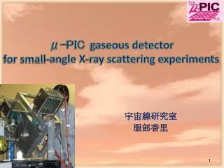
Micro Pixel Chamber における 電子ドリフトおよびガス増幅の シミュレーション. 放電に関する考察と電極構造の最適化. 京都大学 永吉勉. Micro Pattern Gas Detector 研究会. Contents. Micro Pixel Chamber とその現状 Maxwell / Garfield について 放電現象とその考察 電極構造最適化への試み. 10cm. Micro Pixel Chamber ( m -PIC). PCB technology Pixel electrode 2D readout. 100 m m.

E N D
Micro Pixel Chamberにおける電子ドリフトおよびガス増幅のシミュレーション 放電に関する考察と電極構造の最適化 京都大学 永吉勉 Micro Pattern Gas Detector 研究会
Contents • Micro Pixel Chamberとその現状 • Maxwell / Garfieldについて • 放電現象とその考察 • 電極構造最適化への試み
10cm Micro Pixel Chamber (m-PIC) • PCB technology • Pixel electrode • 2D readout 100mm • 400m pitch electrodes • 256 anodes and 256 cathodes Detection area = 100cm2
0.5mm slits Gas gain Max: 1.6×10⁴ 104 Ar / C2H6 (90 / 10) Ar / C2H6 (80 / 20) 103 400 Anode voltage [V] Max: 1.6×10⁴ Stable: ~6000 Gas gain Length along the edge [mm] Performance of m-PIC Max gas gain …limited by discharge position resolution σ=120mm
DRIFT[clock] Cathode[cm] Anode[cm] proton( ~1MeV) CP + m-PICgain ~ 104 目標 ガス増幅率105、放電なしで数ヶ月以上の安定動作 m track (Cosmic ray) m-PICの現状 Gas gain 5000~10000のときのμ飛跡の図 • ガス増幅率は104を超えている • MIP検出にはあと数倍高くしたい • この条件での安定動作は厳しい Gas gain 数万のときのμ飛跡の図 • ガス増幅率を制限しているのは放電 • 放電の原因を特定したい
Simulation 3D simulation using MAXWELL and GARFIELD • MAXWELL • 3D structure • Finite element method • GARFIELD • Electron drift • Gas multiplication Field map Expectedperformance MAXWELL GARFIELD
(anode) 10mm 10mm Damaged electrode(anode) (cathode) Nagae et al., NIM A 323 (1992) 236 Discharge Possible mechanism … • High ionization (avalanche size >108 electrons) • Malter effect (ポリマー膜の絶縁破壊) • 絶縁層への電子の蓄積 帯電 沿面放電 • カソード端からのField emission Damaged electrode of MSGC 電子収集効率 ~90% ~10% charging-up 電子ドリフト終端点分布
104 放電をなくす試み: チタンコーティング 効果なし Gas gain 103 460 560 Anode voltage [V] Ti-coat m-PIC Normal m-PIC 10cm チタンコートm-PIC • もともとはMSGCで陽イオン蓄積を防ぐためのもの • 電子蓄積を防ぐ 放電予防? 有機チタンをコーティングしたm-PIC • Gas gain ~ 3000で 動作不安定 • 電子蓄積は放電の 原因ではない?
金属表面付近のポテンシャル ~200kV/cm 電場がないとき x F -eEx I = a E2 exp( – b / E ) 電場があるとき m-PIC電場強度マップ 100-200kV/cm E Field emission • 強電場下で金属表面から電子が放出される • 入射粒子がなくても放電がおこる (E > 数百~千kV/cm) 強電場のあるところ: 電気三重点(triple junction) vacuum(gas) metal(cathode) dielectric
エッチング残り? 100-150kV/cm cathode E > 600kV/cm エッチング残り? Field emission 強電場が生じる場所 エッチング残りなどがあると強電場ができる
Surface flashover 180 基板表面に沿ったTownsend係数 Triple junction 100 104 E field [kV/cm] 103 Townsend [1/cm] 20 102 10 Emitted electrons ~ Case of the current m-PIC ~ 基板表面に沿った電場強度 TJからField emission 基板表面を走りながら ガス増幅 基板表面に沿ってTownsend係数を積分 “ガス増幅率” ~ 5×10⁷ Raether limitに近い
m-PIC + capillary plate (CP) (VmPIC = 520V) 104 Total gas gain 103 1700 1800 VCP [V] 放電の原因は? CP: 鉛の放射性同位体を含む a particle 103-4 electrons/anode • 有機チタンコーティングは効果なし • Capillary plate + m-PICではgas gain > 104で安定動作 2.2×10⁴ 1電極あたり~105個の電子が蓄積するはず(for 1 a particle) 放電の主要な原因はカソードからの電子放出? ドリフト電子蓄積 放電とはならない!!
350 Thickness 5mm 100mm 200mm E field [kV/cm] 100 O r anode cathode (600V) (GND) Optimization 1 ~ Thick insulator m-PIC ~ Thick insulator High field @ anode Low field @ cathode • High gas gain ( > 105) • Discharge-free operation
1010 Triple junction current m-PIC 109 Multiplication 108 Raether limit 沿面ガス増幅率の厚さ依存 (これは前頁?) 107 106 50 100 150 200 Thickness [mm] Optimization 1 ~ Thick insulator m-PIC ~ 基板表面を走る電子の”ガス増幅” 薄い基板:沿面放電の”ガス増幅率”がRaether limitを超える 沿面フラッシオーバ?
5mm thick 200mm thick Optimization 1 ~ Thick insulator m-PIC ~ m-PICの絶縁層を厚くする • カソード端の電場が弱い Field emission起こりにくい • Field emission による“ガス増幅率”が低い • ドリフト電子を効率よく収集 Efficiency ~ 40% Efficiency > 90% 絶縁層を厚くしたいが… • アノードのアスペクト比 > 2 技術的に難しい • 他の方法はないか?
150-200kV/cm < 100kV/cm well-type normal Maxwellによる電場強度マップ Optimization 2 ~ Well-type m-PIC ~ • レーザーで絶縁層を除去 • 電子収集効率 > 98% • カソード端での電場が弱い 放電が起こりにくい • 壁面での放電が問題 改善可能? 電子ドリフト終端点分布
Summary m-PICにおける放電の原因について • 有機チタンコーティングでは放電を防げない • 鉛ガラスCP + m-PICはgas gain > 104で安定動作 • 電場計算 沿面放電の“ガス増幅率” ~ Raether limit 放電の原因はField emissionによる沿面放電 対策 … カソード端での電場を弱くする • 厚い絶縁層を作る • 絶縁層をレーザーで掘り抜く …今のところ、技術的に困難 …GEMで可能ならm-PICでも