Download
1 / 8
80 likes | 217 Views
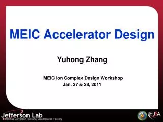
Ion Accelerator Complex for MEIC. January 28, 2010. Ion Sources. Main parameters Emittance Pulse current Pulse length Repetition rate Polarized H ¯ and D ¯ Improve degree of polarization Light ion polarized sources – Demonstrate peak pulse current Heavy Ion Sources (ECR)

E N D
Ion Accelerator Complex for MEIC January 28, 2010
Ion Sources • Main parameters • Emittance • Pulse current • Pulse length • Repetition rate • Polarized H¯ and D¯ • Improve degree of polarization • Light ion polarized sources – • Demonstrate peak pulse current • Heavy Ion Sources (ECR) • Demonstrate ~2 mA over 250 sec • New generation of ECR sources (56 GHz) in afterglow mode • Heavy Ion Sources (EBIS) • Charge per pulse is low – longer accumulation time in the pre-booster
Multi-beam Ion Linac • Linac layout • 200 MeV for protons and 70 MeV/u for heavy ions seems close to optimal for accumulation of required current with specified beam quality in the pre-booster • SRF technology for ion beam acceleration is well established • Further cost reduction is expected due to many new projects • However, it is unlikely that the cost of the linac drops below $100M Ion Sources RFQ IH QWR QWR HWR DSR MEBT Stripper Normal conducting Superconducting
Pre-Booster • Current pre-conceptual design satisfies all specifications required for the collider • Low emittance • High current • Excellent properties of the polarized beams • Demonstrated technology • Multi-turn injection of heavy-ion beams • Electron cooling with DC beams • 2-harmonic acceleration at low frequency • Further R&D due to more challenging beam parameters (low emittance, high current, higher energy,…) • 3D simulation of the injection • 3D simulation of acceleartion
Large Booster • Longer circumference (factor of 4 longer then pre-booster) • Conceptually similar to the pre-booster • Protons from 3 to 12 GeV • Lead Ions from 1.18 GeV/u to ~4.5 GeV/u • Fully stripped before the injection into the L-Booster • Acceleration • Use low frequencies harmonics 4 or 5 • Higher harmonics may not be necessary (to suppress space charge) • Lattice – no issues • Maintain polarization – no significant issues • Emittance, space charge can be controlled well
Forming High Frequency (750 MHz) ion bunches • Concept: • Accelerate ions to high energies with low frequency RF • Create coasting beam – L-Booster or Main Ring • Adiabatically bunch and accelerate – efficiency ~99% is required • Minimize losses • Momentum collimation • Develop 750 MHz cavities with variable frequency in the range of ~10 MHz. • Normal conducting • Can be a mechanical tuner to vary frequency in timescale of a second • Main ring • Protons from 12 to 60 GeV – f ~2MHz for 750 MHz • Lead ions ~4.5 GeV/u to 23 GeV/u - f ~10MHz for 750 MHz
Issues with forming of 750 MHz bunches • Acceleration time – defined by the tuner system in the RF cavities • Mechanical – seconds • Ferrites ? The frequency is high • Acceleration time can be reduced if two RF systems are used: low frequency (~10 MHz) and high frequency with very low f • Main Ring is crowded, is there enough space in the MR for collimation?
Main Ring • Transition energy must be lower ~4 GeV/u • IBS