Download
1 / 24
270 likes | 539 Views
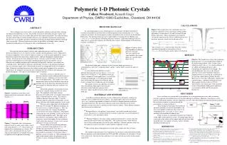
Photonic Crystals in Optical Communications. Mihail M. Sigalas. Agilent Laboratories, Palo Alto, CA. mihail_sigalas@agilent.com. Outline. -Trends in Optical Communications -Photonic Crystals -Numerical Methods -Photonic Crystal Waveguides -Resonators in Photonic Crystals -Conclusions.

E N D
Photonic Crystals in Optical Communications Mihail M. Sigalas Agilent Laboratories, Palo Alto, CA mihail_sigalas@agilent.com
Outline -Trends in Optical Communications -Photonic Crystals -Numerical Methods -Photonic Crystal Waveguides -Resonators in Photonic Crystals -Conclusions
Trends in Optical Communications -Optical interconnects have been replacing electrical interconnects at shorter and shorter distances over time. -Optical interconnects for chip to chip or even within one chip will be needed in the near future. -Very short (microns scale) optical components (waveguides, bends, splitters, resonators) needed to achieve that. -There are two ways to make micron scale optical components: Photonic crystals and high index contrast materials.
n-1/2 n n+1/2 Time H H E E E Finite Difference Time Domain Method • Approximate the space and time derivatives in Maxwell’s equations with • finite differences. • The ``leap-frog’’ scheme for the E and H fields in time: • E and H fields • in space (Yee grid):
Finite Difference Time Domain Method 4. Use absorbing boundary conditions (ABC) to close the space Photonic Crystal ABC
Requirements for photonic crystals interconnects -Should be easily fabricated (2D slab PC are easier to be made than 3D PC) -Should have low propagation and coupling losses. -Most of the current 2D slab PC waveguides have narrow guiding bands with small group velocities. Small group velocities create higher internal and propagation losses. New structures are needed. -Should be easily integrated with active devices (lasers, LEDs).
2D Slab PBG Waveguides Si slab on a SiO2 substrate Triangular Lattice; Lattice constant: a; R/a=0.29; h/a=0.6 Band Gap for even modes (TE-like): 0.242-0.307 c/a High index contrast confinement perpendicular to the slab. Photonic band gap effect within the slab.
2D Slab PBG Waveguides: Circular Air Holes Guiding along a line of circular Air holes with Rd=0.45a Guided Band is narrow with Small group velocity 3D FDTD Calculations Aslo see: Loncar, et.al., J. Opt. Soc. Am. B 18, 1362 (2001)
2D Slab PBG Waveguides: Elliptical Air Holes Guiding along a line of elliptical Air holes with Short axis 0.66a and long axis 1.48a. Guided band covers most of the band gap. Plane Wave Expansion Method Johnson, et.al., Opt. Express 8, 173 (2001) Leaky Modes
2D Slab PBG Waveguides: Elliptical Air Holes Guiding along a line of elliptical Air holes with Ratio of short to long axis 0.45 Good coupling and low propagation losses Short axis: 0.66a, 0.7a, 0.74a
SiO2 (0.15um) Si (0.26um) SiO2 (1um) substrate Fabrication of PC waveguides Alignment Marks Define PC Waveguide SEM of PBG waveguide Silicon Etch Define Ridge Waveguide
Conventional Waveguide Bends Si waveguide on SiO2 120o Bend: ~70% Transmission 60o Bend: ~90% Transmission Good Transmission! Also see: Manolatou et. al., J. Lightwave Techn. 17, 1682 (1999)
PBG vs. Conventional Waveguides • Both types of waveguides could give 100% efficiency • along tight bends. • There is ONLY one difference between the two types: • PBG waveguides can guide light mostly through the air. • However, ONLY 3D photonic crystals can do that.
3D Photonic Crystals Layers of Si rods surrounded by air Ho et. al., Solid State Commun. 89, 413 (1994)
3D PBG Waveguide Bend Photonic Crystal Total Thickness: 20 layers Straight waveguide (Black) Bend (Red) Projection of the 10th and 11th layers
3D PBG Waveguide Splitter Photonic Crystal Total Thickness: 20 layers Straight waveguide (Black) Splitter (Red) Projection of the 10th and 11th layers
3D PBG Waveguide Splitter Guiding mostly through the air 11th Layer 10th Layer
Micro-resonators -Micron sizeresonators needed for sources and detectors. -Micro-resonators also needed for add-drop filters in Wavelength Division Multiplexing. -There are two ways to create micron-size resonators: Photonic crystals and High index contrast materials (micro-disk, micro-ring).
2D Slab PBG Resonators Air Holes in Si slab with SiO2 substrate Lattice constant: a Air holes Radius: 0.29a Mode Volume: ~a^3 Rd/a=0.21, 0.17, 0.11 See also: Vuckovic, et.al., Phys. Rev. E 65, 016608 (2001)
Disk Resonators Si on SiO2 Disk Radius: 2a Disk Thickness: 0.6a Mode Volume: ~p (2a)^2 a=4pa^3
Conclusions -There is a need for micron scale components (waveguides and resonators) for optical communications. -There are two possible candidate materials for building the optical components: Photonic crystals and high index contrast materials. -For waveguides, both types of materials are expected to perform equally well. -However, 3D photonic crystals can guide light mostly through the air. -Photonic crystal resonators are expected to be 5-10 times smaller in size than micro-disk resonators.
Future Work - Loss mechanisms - Theoretical models - Coupling to photonic crystal waveguides