Download
1 / 19
200 likes | 493 Views
Data Communication and Networking. 332 Hardware Components of Data Communications . Lecture Overview. DTE DCE Modem Standards. Data Terminal Equipment. DTE can be virtually any binary digital device that generates, transmits, receivers, or interprets data messages.

E N D
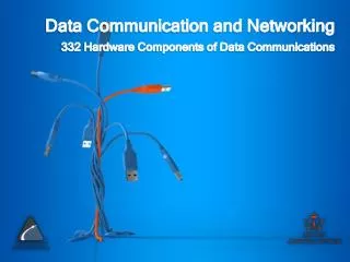
Data Communication and Networking 332 Hardware Components of Data Communications
Lecture Overview • DTE • DCE • Modem Standards
Data Terminal Equipment • DTE can be virtually any binary digital device that generates, transmits, receivers, or interprets data messages. • In essence, a DTE is where information originates or terminates. • DTEs contain the hardware and software necessary to establish and control communications between endpoints in a data communications system. • DTE includes the concept of terminals, clients, hosts and servers. • E.g. video display terminals, printers and personal computer
Data Circuit-Terminating Equipment • Also known as Data Communication Equipment and Data Carrier Equipment • DCE is a general term used to describe equipment that interfaces data terminal equipment to transmission channel, such as an analog telephone circuit. • The output of a DTE can be digital or analog, depending on the application. • In essence, a DCE is a signal conversion device, as it converts signals from DTE to a form more suitable to be transported over a transmission channel. • A DCE also converts those signals back to their original form at the receive end of a circuit.
Data Circuit-Terminating Equipment • Several types of DCEs depending on the type of transmission channel used: • Channel Service Unit (CSU) and Digital Service Unit (DSU) • Used to interface DTEs to digital transmission channels. • Data Modems • Used to interface DTEs to analog telephone networks
Modems Standards • Modems operations for the Telephone line interfacing is standardized by the International Telecommunications Union – part of ITU. • Modem standards are set as ITU-T “V-series” Specifications • When 2 modems attempt to establish a connection a process called “handshaking” takes place. • Three most important things negotiated are the speed, compression techniqueand error control.
Modems Standards (Speed) • Speedis the data transmission rate between DCE to DCE. • Speed depends on line quality • Examples of speeds used today are: • 14400 bps (V.32 bis) • 28800 bps (V.34bis) • 33600 bps (V34 bis -with software enhancement) • 57000 bps (V.90)
Modems Standards (Compression) • Compression the process of reducing the repetitive bits pattern and redundant bits within a data set. • Eg. a text message contains the string XXXXXX, a compression technique code the string into 2 bytes i.e. : • one byte to identify the repetitive character and • one byte to specify the number of times it is repeated. • Compressed file can be sent at a higher speed than uncompressed file. • The two primary standards used for modems are V.42 and the Micro Networking Protocol (MNP) level 5.
Modems Standards (Compression) • V.42generate 4 to 1 data compression ratio depending on the type of file being transmitted. • MNP5 compress data by a factor of 2 to 1. • To benefit from compression the PC must be able to transmit with its connected modem at a rate that is equal to the speed achieved by the compression ratio.
Modems Standards (Error Control) • Error Controlrefers to error detection and correction. • The standards used are V.42 and MNP levels 1 through 4. • V.42 uses cyclic redundancy check (CRC) for error detection and automatic repeat request (ARQ). ARQ prevents the modem from accepting any more data until the defective frame has been retransmitted successfully.
Types of Modem Standards • Most recent series based on the V-series standards published by the ITU-TThree types of modem standards: • V.32 and V.32 bis • V. 34 bis • V 90 • V 92
Modem – V.32 • The V.32 modem uses a combined modulation and encoding technique called trelliscodedmodulation. • Trellis is essentially QAM plus a redundant bit. • The data stream is divided into 4-bit sections. • Instead of a quadbit (4-bit pattern), however, a pentabit (5-bit pattern) is transmitted. • The value of the extra bit is calculated from the values of the data bits. • The extra bit is used for error detection. • The Y.32 calls for 32-QAM with a baud rate of 2400. Because only 4 bits of each pentabitrepresent data, the resulting data rate is 4 x 2400 = 9600 bps
Modem – V.32 bis • The V.32bis modem was the first of the ITU-T standards to support 14,400-bps transmission. • The Y.32bis uses 128-QAM transmission (7 bits/baud with I bit for error control) at a rate of 2400 baud (2400 x 6 = 14,400 bps). • An additional enhancement provided by Y.32bis is the inclusion of an automatic fall-back and fall-forward feature that enables the modem to adjust its speed upward or downward depending on the quality of the line or signal
Modem – V.34bis • The V.34bis modem provides a full-duplex bit rate of 28,800 with a 960-point constellation and a bit rate of 33,600 bps with a 1664-point constellation.
Modem – V.90 • V.90 modems with a bit rate of 56,000 bps are available; these are called 56K modems • These modems may be used only if one party is using digital signaling (such as through an Internet provider). • They are asymmetric in that the downloading rate (flow of data from the Internet service provider to the PC) is a maximum of 56 kbps, while the uploading rate (flow of data from the PC to the Internet provider) can be a maximum of 33.6 kbps • How we arrive at the 56-kbps figure? • The telephone companies sample 8000 times per second with 8 bits per sample. One of the bits in each sample is used for control purposes, which means each sample is 7 bits. The rate is therefore 8000 x 7, or 56,000 bps or 56 kbps.
Modem – V.92 • The standard above V.90 is called V.92. These modems can adjust their speed, and if the noise allows, they can upload data at the rate of 48 kbps. The downloading rate is still 56 kbps. • The modem has additional features: • For example, the modem can interrupt the Internet connection when there is an incoming call if the line has call-waiting service.