Download
1 / 35
370 likes | 906 Views
BNSF Concrete Tie And Fastener Experience. University Of Illinois June 7, 2012. John Bosshart. Outline Fastening Systems. Review of past Fastening experience PR601 1979 E-clips 1986 Safelok 1987 Thorough Testing Future Vossloh 2006 Description / Comparison Thorough lab testing

E N D
BNSF Concrete Tie And Fastener Experience University Of Illinois June 7, 2012 John Bosshart
Outline Fastening Systems • Review of past Fastening experience • PR601 1979 • E-clips 1986 • Safelok 1987 • Thorough Testing • Future Vossloh 2006 • Description / Comparison • Thorough lab testing • Extensive field testing
Outline Concrete Ties • Review of past Concrete tie experience • Lead Line (new construction) 1968 • Eldorado Line Change 1979 • Wendover, Crawford, Leonia 1986 • Increased foot print and capacity 1992 -2004 • MRT – Interspersed Concrete 2002
Lead Line- • New construction project 1968 • Tie did not have the sufficient bending capacity • Initial work trains over the line unloading ballast cracked most of the ties • Expensive lesson • Do not crown new construction subgrade • Provide support under the rail seats
New Construction: El Dorado, Kan. • Installed in 1978 or 1979 -Positive results • Still in service: tangent and light curves • Amtrak designed HD 800# tie • Tie pad and insulator have been replaced with new rail in 1998. • PR601 clips tested in 1998 when rail relay was planned; clips were still worthy of continued service
1986 BNSF 100 vs BNSF 101L 725 lbs. Slump 5” + - 1.5” Concrete compressive 4500psi minimum at transfer 7,000psi at 28 days 18 ea. 0.209” (5.3mm) wires - 260 ksi Stress/wire 6,500 lbs. 8’ 6” Length Side scallop patternsPattern on the bottom Air entrainment 3.5% minimum • 620 lbs. • Slump max of 2” • Concrete compressive • 4500psi minimum at transfer • 6500psi at 28 days. • 28 ea. 0.195” (5.0mm) wires - 225ksi • Stress/wire 5,170 lbs. • Envelope was 8’ 3” long • No lateral resistance pattern except on the bottom • Air entrainment 3.5%
BNSF 100 VS BNSF 101L *AREMA, Chapt. 30, Section 4.4
1986 E-Clip Installations(Sharp Curves And Grade) Wendover Canyon, Crawford Hill, Kootenai Canyon • Crawford Hill • E-clips did not hold rail longitudinally • E-clip failures • Tie skewing • Wendover Canyon and Crawford Hill 100 percent anchored • Problems surfaced with EVA and ester polyurethane in later years
1987 Introduction Safelok System • Clip security • Improved longitudinal restraint • Clip fatigue not evident • EVA tie pads used • “Discovered” that nylon insulators were water-conditioned
Current Fastening Issues • Technical Issues belong to owner and manufacturer/supplier partnership • Clips fatigue • Insulators - Inconsistent production quality
Current Issues (continued) • Rail-seat deterioration • Contributing factors • Different preventive systems • Shoulder wear • Understanding current system shortcomings should lead to improvements of current systems and selecting future systems
Safelok System Still Seeking • Improved rail-seat solutions for steel gangs • Clean the rail seat thoroughly • Protect and repair shoulder wear • Improve insulator • Improper insulator conditioning is still happening • Increased toe load clip to reduce deflection
Insulators Wear ….. Sacrificial member that protects the shoulder
BNSF Proof Testing Insulators • Compression test • 20,000 pounds • 30,000 cycles • Drop impact test
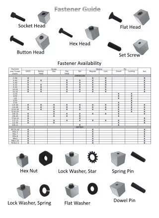
Lag screw Plastic insert 130 190 Gauge-side angle-guide plate Spring clip BNSF field angle-guide plate
Tie Pad Tie pad made of BASF polyurethane Protective sheet prevents RSA
Insulator / Angle Guide Plate Stat’s • Vossloh standard guide plate has 225 percent increase in bearing area beyond Safelok: 58mm vs. 130mm • BNSF’s Vossloh field guide plate is 190mm • 46 percent increase in surface area from 130mm to 190mm
Insulators vs. Angle-Guide Plates • The BNSF field-side angle-guide plate has 327 percent larger surface area than Safeloksystem • Lag screw does not bear any side load. Angle-guide plate load is against the concrete • Angle guide plate flexes under load • Vossloh system has no shoulder wear • Slight angle-guide plate wear has been observed. Safelok insulators have worn out on adjacent ties
Clip or Tension Clamp Over drive stop Spring tension Spring force is roughly 1,000# per 1mm of displacement Standard displacement on a new installation is 15.5 +/- 1.5mm
Set Up on Each Rail Seat • Each arm of the MTS • 32.5k vertical • 16.9k lateral • 1k reverse load to move rail inward • Sand #0, #16, #24, #40 grit • Water - 1 drip/second • Heat, cold (-40º F) • 2.5 cycles/second
Initial “Tests” Installations • UPRR’s ¼-mile at Dragoon, Ariz., 1987 • C1053, 2-D curve, 30MGT DBL TRK • Reviewed August 2006, showed no problems except tie pads • BNSF 200 ties at Mountainair, N.M. • Installed April 5, 2006 • 180 MGT, M2, 2-D, 30’, 180MGT, 55 mph • Blacktail, Mont., 200 ties • Installed August 2006, MT2, 25-30 mph, 90MGT, 2.2 percent grade
“Tests” Installed: Continued • “Twins” Minneapolis, Minn., project • Installed 3,000 ties October 2007 • Oregon Trunk • 1,200 ties installed October 2007 • 12º 30’ curve, 10 mph • Butte Subdivision: “Crawford Hill” • 1,200 ties, 1.8 percent grade, 7º 58” curve
Preload of the Vossloh fasteners at the ROCLA tie plant No “spidering” for de-stressing Large angle-guide plate for field side. 327 percent larger than Safelok. 190mm Reduced “insulator” wear Safelok preloading is limited to clip- and tie-pad sets Small crew must replace clips and handle a few insulators Insulator is 58mm wide Insulators are replaced as necessary Advantages
Lag screw does not bear side load Lag screw and insert can be replaced Derailment-damaged clips and lags can be replaced Clips can not be over driven Clips have a rotation stop Shoulder takes the entire load Shoulders wear Clip and shoulder damage normally result in tie replacement Clips can be over driven Clips do not have a drive stop Advantages (continued)