Download
1 / 19
230 likes | 542 Views
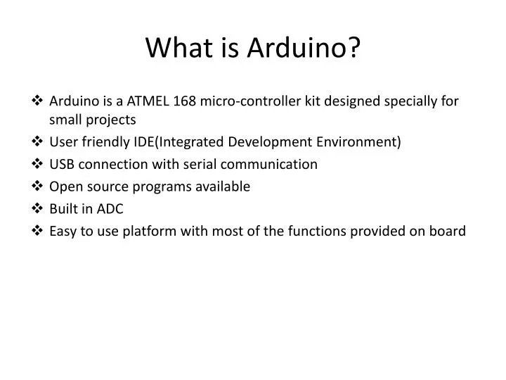
What is Arduino ?. Arduino is a ATMEL 168 micro-controller kit designed specially for small projects User friendly IDE(Integrated Development Environment) USB connection with serial communication Open source programs available Built in ADC

E N D
What is Arduino? • Arduino is a ATMEL 168 micro-controller kit designed specially for small projects • User friendly IDE(Integrated Development Environment) • USB connection with serial communication • Open source programs available • Built in ADC • Easy to use platform with most of the functions provided on board
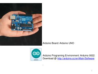
Introduction to Arduino 8 BIT DIGITAL PORT WITH PWM PINS 8 BIT DIGITAL PORT WITH COMMUNICATION PINS ON BOARD CRYSTAL USB CONNECTOR FOR COMPUTER INTERFACING RESET SWITCH ATMEL 168 EXTERNAL SUPPLY – 6V DC POWER PORT ADC PINS
Why Arduino? • Arduino has multiple inbuilt features and acts as a combination of 10 bit analog to digital converter(ADC), storage and microprocessor. • Arduino comes up with its own software for analyzing, processing and calculation of unknown parameters. • It provides a facility to write programs, compile them and program the microcontroller all by itself. • It can take 6 analog inputs and a time and process all of them without any difficulty. • There are 2 digital 8 pin ports available and they can be used for interfacing with LCD, LEDs, to drive an other circuit and so on.
Sample programs • ADC – Analog to Digital Converter • Takes analogue input from Potentiometer • Converts 0-5V analog signal to 0-1023 Digital values • Displays it on screen using serial communication • Displays it on 16x 8 LCD
Analog to Digital Converter • CODE : • void setup() { • Serial.begin(9600); //begin serial communication with computer • } • //void loop runs continuously on µc • void loop() { • intsensorValue = analogRead(A0); //reads analogue pin A0 • Serial.println(sensorValue, DEC); //prints it on serial monitor • }
LCD Interfacing • CODE: • LiquidCrystallcd(12, 11, 5, 4, 3, 2); • void setup() { • lcd.begin(16, 2); // set up the LCD's number of columns and rows: • lcd.print("hello, world!"); // Print a message to the LCD. • } • void loop() { • // set the cursor to column 0, line 1 • // (note: line 1 is the second row, since counting begins with 0): • lcd.setCursor(0, 1); • lcd.print(millis()/1000); // print the number of seconds since reset: • }
Hardware is reduced Usb port of computer 16 x 8 LCD display Analog signal ARDUINO KIT
Frequency calculation for square wave • Firstly, a square wave is generated using a 555(timer circuit). • The values of R,C are adjusted such that the frequency of output is close to 60Hz. • This square wave signal is given to one of the analog pins of Arduino. • Code for the frequency calculation is written, verified and programmed using the Arduino software. • The calculated frequency is displayed in the serial monitor of the software or using an LCD.
Frequency calculation for square wave SERIAL MONITOR ARDUINO KIT LCD
Measurement of live Power System Frequency Taking samples from actual 230V AC Supply
The Problem ARDUINO KIT 0-5 V DC SIGNAL POWER SUPPLY 230 V AC SIGNAL TRANSFORMER - 2.5 TO 2.5 V & DCOFFSET OF 2.5 V DC
Live frequency estimation by Arduino • The live power signal of 230V magnitude is stepped down by a transformer to 3V. • This AC signal of 3V is then fed to one of the analog pins of Arduino. • Arduino microcontroller is able to read the input only during its positive half cycle. • A set of 250 samples of this sinusoidal wave is taken by the kit which has a sampling time interval of .112ms. • As per the traditional zero cross-over method, the frequency of the live signal is calculated.
Live frequency estimation by Arduino Live AC signal 230V/3V Transformer ARDUINO KIT SERIAL MONITOR LCD
Taking all samples of the live signal • Since , the Arduino cannot be fed with an AC signal of high magnitude, the signal is first brought to an AC wave of 6V magnitude using a step down transformer. • This wave is given to the inverting pin of 741 Op-Amp IC using a variable resistor such that the output due to this signal alone is 2V. • A dc voltage is fed to the non inverting pin of 741 so that the output due to this signal alone is 3V. • This sinusoidal non AC signal varies from 0V to 5V. • This signal is finally given to one of the analog pins of the Arduino. • Analog-serial-input code is programmed into Arduino and samples of the signal can be seen in the serial monitor every 1 ms.
Taking all samples of the live signal ARDUINO KIT Serial Monitor
Limitations of Arduino • Calculations of very high frequency signals is not possible using Arduino as the sampling rate of ADC is low. • The input signal must be non AC and must posses a magnitude of less than 5V. • Heavy mathematical functions like inverse trigonometry, modulus • operation, complex equations cannot be performed by the Arduino software.