Download
1 / 1
10 likes | 116 Views
Length of Power Cables = 140 Meters. Length of Power Cables = 140 Meters. 3.5 V. 3.5 V. Cable Resistance = 4.5 Ohms. Cable Resistance = 4.5 Ohms. 10 Chip Hybrid – SCT Module for LHC. 10 Chip Hybrid – SCT Module for LHC. 10.25 V. 10.25 V. 4088 Cables. 4088 Cables. Voltage Drop = 6.75 V.

E N D
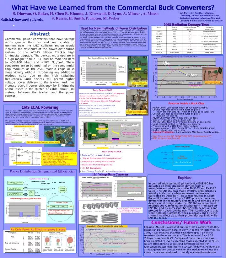
Length of Power Cables = 140 Meters Length of Power Cables = 140 Meters 3.5 V 3.5 V Cable Resistance = 4.5 Ohms Cable Resistance = 4.5 Ohms 10 Chip Hybrid – SCT Module for LHC 10 Chip Hybrid – SCT Module for LHC 10.25 V 10.25 V 4088 Cables 4088 Cables Voltage Drop = 6.75 V Voltage Drop = 6.75 V 1.5 amps 1.5 amps Counting House Counting House 1.3 V 1.3 V 20 Chip Hybrid – Si Tr Module for Hi Luminosity 20 Chip Hybrid – Si Tr Module for Hi Luminosity 12.1V 12.1V Voltage Drop = 10.8V Voltage Drop = 10.8V 2.4 amps 2.4 amps 13 V 13 V 20 Chip Hybrid – Si Tr Module for Hi Luminosity 20 Chip Hybrid – Si Tr Module for Hi Luminosity 1.3 V 1.3 V 14.08 V 14.08 V Voltage Drop = 1.08 V Voltage Drop = 1.08 V 2.4 amps 2.4 amps 0.24 amps 0.24 amps Abstract Commercial power converters that have voltage ratios greater than ten and are capable of running near the LHC collision region would increase the efficiency of the power distribution system of the ATLAS Silicon Tracker high luminosity upgrade. The devices must operate in a high magnetic field (2T) and be radiation hard to ~50-100 Mrad and ~1015 Neq/cm2. These converters are to be mounted on the same multi-chip modules as the ASIC readout chips or in close vicinity without introducing any additional readout noise due to the high switching frequencies. Such devices will permit higher voltage power delivery to the tracker and thus increase overall power efficiency by limiting the ohmic losses in the stretch of cable (about 100 meters) between the tracker and the power sources. Need for New methods of Power Distribution Presently LHC inner detector electronics use DC power supplies located in the counting house that feed low voltage power over a long distance (30 m for CMS and 140 m for ATLAS detector). Here we focus on the powering of the silicon tracker for the high luminosity LHC that shall result in x10 higher luminosity and use x10 more detecting elements. The “Power Delivery with Existing SCT Cables” plot illustrates the problem. At present 10.25 V power from the counting house is delivered by 4088 power cables each with a resistance of 4.5 Ω. The 10 chip ASIC readout chip hybrid Kapton PCB needs 1.5 amps @ 3.5 Volts. The bar graph shows the power delivery efficiency of ~33%. In an upgraded ASIC design with finer lithography and x2 more chips, the voltage drops to 1.3 V and with the same cables the power delivery efficiency drops to 10%. By inserting a DC-DC with x10 voltage converter on the 20 chip hybrid Kapton PCB, the efficiency climbs to over 80%. CMS ECAL Powering Enpirion: In our radiation testing Enpirion device EN5360 has outlasted all other irradiated devices from all manufacturers, while the similar EN5365 and EN5382 failed. The EN5360 was made by IHP Microelectronics foundry in Germany while successor devices are fabricated by Dongbu HiTek semiconductor in South Korea. Both are on 0.25 mm CMOS process, but some differences in the foundry processes and perhaps in the device circuit design make the EN5360 radiation hard. Recently Los Alamos National Laboratory irradiated an EN5360 and its successor EN5365 with heavy ions and protons for space satellite use. Their conclusion is that while both are suitable for their purposes, the EN5360 showed no effect up to their proton dosage limit while EN5365 failed. What Have we Learned from the Commercial Buck Converters? S. Dhawan, O. Baker, H. Chen R. Khanna, J. Kierstead, D. Lynn, A. Mincer , A. Musso S. Rescia, H. Smith, P. Tipton, M. Weber Yale University, Brookhaven National Laboratory, National Semiconductor Corp, Rutherford Appleton Laboratory, New York University & Rutherford Appleton Laboratory Satish.Dhawan@yale.edu 2008 Radiation Damage Tests Enpirion 5360 before and after radiation, Vin = 5.5V 100 90 After 80 Before 70 60 Before Efficiency (%) 50 40 Note – Device #2 Survived Previous Radiation Run Evaluation Boards #3 Aug-4-2008 After 100 M rads February 2007 30 #2 Aug-4-2008 #1 Aug-4-2008 20 #3 Aug-29-2008 • Tests Done in 2007 • Radiation Test – Enpirion 6 amp Device 0.25 µm CMOS – 100 Mega rads • Evaluation Boards: Enpirion, Linear Technology, Micrel, MPS, TI etc • Air Coil Tests on Chips with External Inductors • Pick up Noise: RHIC Polarimeter Silicon with Analog Readout • RF Leakage • Noise and Pickup Tests - ATLAS Silicon Tracker Module at RAL • Magnetic Field Vout increased 1in 900 @ 7T • Load Efficiency Tests • Noise Same PCB Tests: DC-DC Converter on the Hybrid @ BNL & Yale • Antenna Effect Tests 10 0 0 0.5 1.0 1.5 2.0 2.5 3.0 3.5 4.0 4.5 Output Current (amps) • Features inside a Buck Chip • Power Down: Low power mode. Shut output switches • Output High side current limit pulse by pulse • (turn off high side FET. After 16 times go to soft Start) • Output Low side current limit pulse by pulse • (turn off low side FET) • Power OK if Vout with in 10% of set voltage • Vout overvoltage > Disable high side FET • Thermal Shutdown on over temp. Restore on cool down • Good thermal contact to PCB for heat removal • Produce 5V with a LDO from higher voltage • Current monitor 1000:1 Sense FET or 10 mV Resistor shunt • Under voltage Input protection • External Protection > Limit Absolute Max Power Supply Voltage • Slow Turn on but NO SLOW TURN OFF-Inductive Kick ??? • ASIC to have slow Turn off There is a clear need for a new system of power delivery to the upgraded Atlas Silicon Tracker for the SLHC. Conventional powering will result in an efficiency of power delivery to the detector of about 10% with existing cables whose size are limited in cross section due to space and mass constraints. A system featuring DC-DC converters with voltage ratios of ten will result in an estimated efficiency on the order of 70-80% with existing cables. One approach to DC-DC conversion utilizes the buck regulator architecture. As DC-DC buck converters are commonly used in the commercial market, we have been surveying and testing currently available devices to understand the present state of the art. 7 Tesla Superconducting Magnet: Persistent Mode 1 CMS Trigger Tower Si Sensor 8x10 cms Noise from Buck cab be easily shielded Buck CMS 32.K Trigger Towers = 50 K amps CMS 32.K Trigger Towers = 50,000 amps LDO 12V Power to Hybrids Si Sensor 8x10 cms 5 V 1.2V • Tests Done in 2008 • Radiation Test – A dozen devices- • Why are Enpirion chips (IHP Foundry) Rad Hard ? • Combination of Foundry & Circuit Design • Discuss with IHP, Chip Designers, etc • Air Coil Developments • Load Efficiency Tests for 10:1 Voltage Conversion ratio Vin= 12 V • Low Cost: An ASIC + Inductor + Caps • 10:1 Voltage Ratio @ 1 MHz • High Side switch on for 100 nsec • Low Side switch on for 900 nsec • High Speed CMOS Switching Processor • Switching Losses – High Side • Conduction Losses – Low Side • In Future speed increase to 20 MHz ENB GND Small Plug-in Card Vout = 2.5 / 1.3 V 6 amps Enable GND Size = 2 cms x 3cms 10:1 Buck Converter Power Good Power Distribution Schemes and Efficiencies 10:1 Voltage Ratio Converter Non Linear output Conductance Effect of output Conductance X 10 DC-DC Power Converter 2 Cascaded Stages Stage 1 Stag 2 Vout Vin Coils under Development By William B. Kuhn @ Kansas State University Each Stage Efficiency = 0.8 Overall Efficiency = 0.64 Conclusions/ Future Work A proximity effect is seen in the spiral coils Enpirion EN5360 is a proof of principle that a commercial COTS device can be radiation hard. In our visit to the HP factory in Nov 2008, it was revealed that they have developed 12 Volt FET transistors in the same process. This is essential for a 10:1 Voltage conversion BUCK. Samples of these transistors have been irradiated to levels exceeding those expected at the SLHC. We are attempting to understand differences in the IHP fabrication process that lead to a successful device. Additionally, as next generation devices come on the market we will use the infrastructure we developed to quickly evaluate these devices 100 Air Coils Proximity Effect increases Losses Medium coils together 90 Medium coils apart 80 70 60 Efficiency (%) 62 mil, 2 oz Cu away from coils 50 40 15 mil, 2 oz Cu away from coils 30 15 mil, 2 oz Cu towards coils 20 10 62 mil, 2 oz Cu towards coils 0 0 0.5 1.0 1.5 2.0 2.5 3.0 Output Current (amps)