Download
1 / 53
530 likes | 535 Views
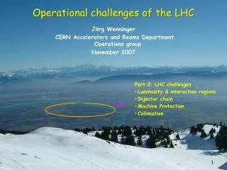
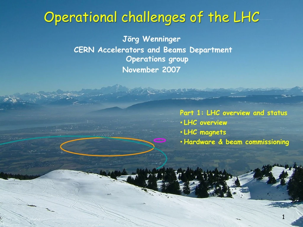
Operational challenges of the LHC. J örg Wenninger CERN Accelerators and Beams Department Operations group November 2007. Part 1: LHC overview and status LHC overview LHC magnets Hardware & beam commissioning. Outline. LHC overview LHC magnet system LHC commissioning Luminosity

E N D
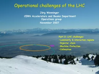
Operational challenges of the LHC JörgWenninger CERN Accelerators and Beams Department Operations group November 2007 • Part 1: LHC overview and status • LHC overview • LHC magnets • Hardware & beam commissioning
Outline • LHC overview • LHC magnet system • LHC commissioning • Luminosity • LHC injector chain • Machine protection • Collimation Part 1 Part 2
LHC History 1982 : First studies for the LHC project 1983 : Z0/W discovered at SPS proton antiproton collider (SppbarS) 1989 : Start of LEP operation (Z boson-factory) 1994 : Approval of the LHC by the CERN Council 1996 : Final decision to start the LHC construction 1996 : LEP operation > 80 GeV (W boson -factory) 2000 : Last year of LEP operation above 100 GeV 2002 : LEP equipment removed 2003 : Start of the LHC installation 2005 : Start of LHC hardware commissioning 2007 : First sector at 1.9K, all magnets at 1 TeV. 2008+ : Expected LHC commissioning with beam
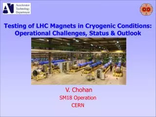
7 years of construction to replace LEP: 1989-2000 in the same 26.7 km tunnel by LHC : 2008-2020+ CMS ATLAS The CERN Beschleuniger Komplex LHC LHCB Control room SPS ALICE CERN (Meyrin) Rüdiger Schmidt Bullay Oktober 2007 4
Tunnel circumference 26.7 km, tunnel diameter 3.8 m Depth : ~ 70-140 m – tunnel is inclined by ~ 1.4%
LHC Layout • 8 arcs. • 8 long straight sections (insertions), ~ 700 m long. • beam 1 : clockwise • beam 2 : counter-clockwise • The beams exchange their positions (inside/outside) in 4 points to ensure that both rings have the same circumference ! Beam dump blocks IR5:CMS IR6: Beam dumping system IR4: RF + Beam instrumentation IR3: Momentum collimation (normal conductingmagnets) IR7: Betatron collimation (normal conductingmagnets) The main dipole magnets define the geometry of the circle ! IR8: LHC-B IR2:ALICE IR1: ATLAS Injection ring 2 Injection ring 1
In total > 50 km of beam lines Beam 2 5 LHC 6 4 Beam 1 7 3 TI8 SPS 2 8 TI2 Booster 1 protons LINACS Top energy/GeVCircumference/m Linac 0.12 30 PSB 1.4 157 CPS 26 628 = 4 PSB SPS 450 6’911 = 11 x PS LHC 7000 26’657 = 27/7 x SPS CPS Ions LEIR Note the energy gain/machine of 10 to 20 – and not more ! The gain is typical for the useful range of magnets !!!
LHC – yet another collider? • The LHC surpasses existing accelerators/colliders in 2 aspects : • The energy of the beam of 7 TeV that is achieved within the size constraints of the existing 26.7 km LEP tunnel. • LHC dipole field 8.3 T • HERA/Tevatron ~ 4 T • The luminosity of the collider that will reach unprecedented values for a hadron machine: • LHC pp ~ 1034 cm-2 s-1 • Tevatron pp 2x1032 cm-2 s-1 • SppbarS pp 6x1030 cm-2 s-1 • The combination of very high field magnets and very high beam intensities required to reach the luminosity targets makes operation of the LHC a great challenge ! A factor 2 in field A factor 4 in size A factor 100 in luminosity
y s B v F x Field challenges The force on a charged particle is given by the Lorentz force which is proportional to the charge, and to the vector product of velocity and magnetic field: • To reach a momentum of 7 TeV/c given the LHC (LEP) bending radius of 2805 m: • Bending field B = 8.33 Tesla • Superconducting magnets • To collide two counter-rotating proton beams, the beams must be in separate vaccum chambers (in the bending sections) with opposite B field direction. • There are actually 2 LHCs and the magnets have a 2-magnets-in-one design!
Luminosity challenges The event rate N for a physics process with cross-section s is proprotional to the collider Luminosity L: k = number of bunches = 2808 N = no. protons per bunch = 1.15×10¹¹ f = revolution frequency = 11.25 kHz s*x,s*y = beam sizes at collision point (hor./vert.) = 16 mm • To maximize L: • Many bunches (k) • Many protons per bunch (N) • A small beam size s*u = (b *e)1/2 • b*: characterizes the beam envelope (optics), varies along the ring, mim. at the collision points. • e: is the phase space volume occupied by the beam (constant along the ring). High beam “brillance” N/e (particles per phase space volume) Injector chain performance ! Small envelope Strong focusing !
The price of high fields & high luminosity… • When the LHC is operated at 7 TeV with its design luminosity & intensity, • the LHC magnets store a huge amount of energy in their magnetic fields: • per dipole magnet Estored = 7 MJ • all magnets Estored = 10.4 GJ • the 2808 LHC bunches store a large amount of kinetic energy: • Ebunch = N x E = 1.15 x 1011 x 7 TeV = 129 kJ • Ebeam = k x Ebunch = 2808 x Ebunch= 362 MJ • To ensure safe operation will be a major challenge for the LHC operation crews ! • Protection of the machine components from the beam is becoming a major issues for all new high power machines (LHC, SNS, …). > 1000 x above damage limit for accelerator components !
Stored Energy • Increase with respect to existing accelerators : • A factor 2 in magnetic field • A factor 7 in beam energy • A factor 200 in stored energy
Comparison… The energy of an A380 at 700 km/hour corresponds to the energy stored in the LHC magnet system : Sufficient to heat up and melt 12 tons of Copper!! • 90 kg of TNT The energy stored in one LHC beam corresponds approximately to… • 8 litres of gasoline • 15 kg of chocolate It’s how ease the energy is released that matters most !!
Superconductivity • The very high DIPOLE field of 8.3 Tesla required to achieve 7 TeV/c can only be obtained with superconducting magnets ! • The material determines: Tccritical temperature Bc critical field • The cable production determines: • Jc critical current density • Lower temperature increased current density higher fields. • Typical for NbTi @ 4.2 K 2000 A/mm2 @ 6T • To reach 8-10 T, the temperature must be lowered to 1.9 K – superfluid Helium ! Bc Tc
The superconducting cable 6 m 1 mm A.Verweij Typical value for operation at 8T and 1.9 K: 800 A width 15 mm Rutherford cable A.Verweij
Coils for dipoles Dipole length 15 m The coils must be aligned very precisely to ensure a good field quality (i.e. ‘pure’ dipole)
Iron Non-magnetic collars Beam Superconducting coil Dipole field map - cross-section B = 8.33 Tesla I = 11800 A L = 0.1 H
Ferromagnetic iron Non-magnetic collars Superconducting coil Beam tube Steel cylinder for Helium Insulation vacuum Vacuum tank Supports Weight (magnet + cryostat) ~ 30 tons, Length 15 m Rüdiger Schmidt 19
Dipole magnet production challenges • The field quality must be excellent: • - Relative field errors due to multipoles much less than 0.1 %. • - The coils/collars must be positioned to some 10 m. • The geometry must be respected – and the magnet must be correctly bent (‘banana’ shape) to follow the curvature of the trajectory. • All magnets had to be produced in time, delivered to CERN, installed in the cryostats, cold tested, and finally installed into the LHC tunnel. • The magnets must reach a field of at least 8.3 Tesla, and possibly 9 Tesla.
First dipole lowered on 7 March 2005 Only one access point for 15 m long dipoles, 35 tons each
LHC arc lattice : not just dipoles • Dipole- und Quadrupol magnets • Provide a stable trajectory for particles with nominal momentum. • Sextupole magnets • Correct the trajectories for off momentum particles (‚chromatic‘ errors). • Multipole-corrector magnets • Sextupole - and decapole corrector magnets at end of dipoles • Used to compensate field imperfections if the dipole magnets. To stabilize trajectories for particles at larger amplitudes – beam lifetime ! • ~ 8000 superconducting magnets ae installed in the LHC
Regular arc: Magnets 1232 main dipoles + 3700 multipole corrector magnets (sextupole, octupole, decapole) 392 main quadrupoles + 2500 corrector magnets (dipole, sextupole, octupole) J. Wenninger - ETHZ - December 2005 23
Connection via service module and jumper Static bath of superfluid helium at 1.9 K in cooling loops of 110 m length Supply and recovery of helium with 26 km long cryogenic distribution line Regular arc: Cryogenics J. Wenninger - ETHZ - December 2005 24
Beam vacuum for Beam 1 + Beam 2 Insulation vacuum for the magnet cryostats Insulation vacuum for the cryogenic distribution line Regular arc: Vacuum J. Wenninger - ETHZ - December 2005 25
Along the arc about several thousand electronic crates (radiation tolerant) for: quench protection, power converters for orbit correctors and instrumentation (beam, vacuum + cryogenics) Regular arc: Electronics J. Wenninger - ETHZ - December 2005 26
Complex interconnects Many complex connections of super-conducting cable that will be buried in a cryostat once the work is finished. This SC cable carries 12’000 A for the main dipoles CERN visit McEwen
Vacuum chamber • The beams circulate in two ultra-high vacuum chambers made of Copper that are cooled to T = 4-20 K. • A beam screen protects the bore of the magnet from image currents, synchrotron light etc from the beam. 50 mm 36 mm Beam screen Beamenvel. ~ 1.8 mm @ 7 TeV Cooling channel (Helium) Magnet bore
Operational margin of SC magnet The LHC is ~1000 times more critical than TEVATRON, HERA, RHIC Applied Field [T] Bccritical field Bc Quench with fast loss of ~106-7 p ~0.01-0.1 ppm of the total int. 8.3 T / 7 TeV QUENCH Tccritical temperature quench with fast loss of ~1010 p ~ 0.01% of total int. Tc 0.54 T / 450 GeV 1.9 K 9 K Temperature [K]
‘Cohabitation’ • Even to reach a luminosity of 1033 cm-2 s-1, i.e. 10% of the design, requires unprecedented amounts of stored beam energy. • The stored energy will be circulating a few cms from extremely sensitive super-conducting magnets, which can quench following a fast loss of less than 1 part per million of the beam: • >>> requires a very large collimation system (> 100 collimators). • LHC commissioning has to be much more rigorous than what was done for previous machines – no shortcuts and dirty ‘tricks’ can be used to go ahead as soon as the intensities exceed a few % of the design. • >>> Predictions on the commissioning duration are particularly tricky!
LHC Commissioning • Commissioning of the LHC equipment (‘Hardware commissioning’) has started in 2005 and is now in full progress. This phase includes: • Testing of ~10000 magnets (most of them superconducting). • 27 km of cryogenic distribution line (QRL). • 4 vacuum systems, each 27 km long. • > 1600 magnet circuits with their power converters (60 A to 13000 kA). • Protection systems for magnets and power converters. • Checkout of beam monitoring devices. • Etc…
Hardware commissioning sequence The present LHC commissioning phase is designated as ‘Hardware Commissioning’. The main job is the commissioning of the magnets and their powering systems. When all magnets of one of the eight LHC sectors installed and interconnected: • Pumping vacuum system to nominal pressure. • Cooling down to 1.9 (4.5) Kelvin. • Connection of the power converter to the magnets. • Commissioning of the power converter + interlock system + magnet protection system (low current). • Commissioning of magnet powering + magnet protection system (high current). • Powering of all magnets in a sector to nominal current. • This commissioning sequence is run individually on each of the 8 LHC sectors (arcs).
From 300K to 80K pre-cooling with 1200 tons of liquid N2 (60 trucks !). Three weeks for first sector. • From 80K to 4.5K. Cool-down with liquid He refrigerators. Three weeks for the first sector. 4700 tons of material to be cooled. • From 4.5K to 1.9K. Cold compressors at 15 mbar. Four days for the first sector. • He inventory : 100 tons (entire LHC). LHC Sector 78 – First cooldown
Commissioning status • Magnet production is completed. • Installation and interconnections finished for magnets. Some components still missing (collimators…). • Cryogenic system : • - One sector (IR8IR7) was cooled down to 1.9 K in June/July 2007. • - Cool-down of 4 (1/2 LHC) sectors starting/in progress (until Christmas). • Powering system: • - Power converter commissioning finished. • - Cool-down and commissioning of the first complete sector (7-8) was performed in June/July 2007: • >> All circuits with individual magnets have been commissioned (except triplets). • >> The main magnets were commissioned to 1 TeV: limited by electrical non-conformities that have been repaired during a warm up of the sector September-October. • - Main commissioning campaign starts in December 2007. • Other systems (RF, beam injection and extraction, beam instrumentation, collimation, interlocks, etc) are essentially on schedule for first beam in 2008.
Commissioning problems… • Given that: • The LHC is of unprecedented complexity, • The LHC performance/technology is pushed to the limits, it is not really surprising that the history of the LHC is filled with more or less severe problems that were related to dipole magnets, cryogenics distribution line, collimators… Two recent problems that concern the machine commissioning: • ‘Inner triplets’ • RF fingers
The (inner) ‘Triplets’ • The large aperture quadrupoles called ‘inner triplets’ are high gradient and large aperture magnets that provide the focussing for the collision point in both planes. They are provided as part of the US & JAPAN contributions to CERN : • - Large beam size ~ 100 x size at IP • - Large beam separation from crossing angle ~ 12 mm • Beam sizes : • at IP (ATLAS, CMS) 16 mm • in the triplets ~1.6 mm • in the arcs ~0.2 mm
Triplet problems • In February 2007 a triplet magnet in point 5 was damaged during a (routine) pressure test. The support that holds the magnet in the cryostat could not sustain the longitudinal force during the pressure test. • A crash programme was initiated in collaboration with FNAL to repair the magnets, partly in situ. • All magnets are now repaired. The faulty support
‘RF fingers’ problems • RF bellows are used to maintain electrical contact between adjacent pieces of vacuum chamber (essential for beam stability). • The bellows must cope with the thermal expansion of ~ 4 cm between 1.9 K and room temperature (when the magnets are cooled down/warmed up). • Bellows are installed at every interconnection (1700 in total).
Damaged bellows • RF fingers that bend into the beam are a classic problem for accelerators. RHIC suffered a lot from it… • So no excuses for not being careful in design and manufacturing ! • And yet it happened ! X-ray imaging of some bellows revealed bend fingers in the sector that was tested in July and warmed up since then for repair.
Cause & solution for RF fingers • The fingers bend due to a combination of a wrong ‘finger angle’ PLUS a gap between the magnet apertures larger than nominal (still inside specification). • Only few interconnects are affected. • Complete survey of one sector was performed using X-ray techniques. • Repair is not difficult…once the bad fingers are found. • >> This problem will stay around until every sector is warmed up again in 200X… • ‘Solution’: • A small (ping-pong size) ball equipped with a 40MHz transmitter is blown through the beam vacuum pipe with compressed air. • Beam position monitors are used to follow the ball as it rolls inside the vacuum chamber until it stops or exits on the other end..
Injector status : beam at the gate to the LHC • The LHC injectors are ready after a long battle to achieve the nominal beam brightness: instabilities, e-clouds etc. • The nominal LHC beam can be produced at 450 GeV in the SPS. TV screen at end transfer line Beam image taken less than 50 m away from the LHC tunnel in IR8 (LHCb) !
Latest ‘schedule’ Pushed to the limit – no contingency ! Expect changes … !!!!!! Mar. Mar. 10 10 11 11 12 12 13 13 Apr. Apr. 14 14 12 23 34 45 56 67 78 81 15 15 16 16 17 17 May May 18 18 19 19 20 20 21 21 Jun. Jun. 22 22 23 23 24 24 25 25 26 26 Jul. Jul. 27 27 28 28 29 29 30 30 Aug. Aug. 31 31 32 32 33 33 34 34 Sep. Sep. 35 35 36 36 37 37 2007 2007 38 38 39 39 Oct. Oct. 40 40 41 41 42 42 Consolidation 43 43 Nov. Nov. 44 44 45 45 46 46 47 47 48 48 49 49 Dec. Dec. 50 50 51 51 52 52 . Jan. Jan. 01 01 02 02 03 03 04 04 05 05 Feb. Feb. 06 06 07 07 08 08 09 09 Mar. Mar. 10 10 11 11 12 12 13 13 Apr. Apr. 14 14 15 15 16 16 17 17 18 18 May May 19 19 20 20 21 21 22 22 Jun. Jun. 23 23 24 24 25 25 Machine Checkout 26 26 Jul. Jul. 27 27 28 28 29 29 BeamCommissioning to 7 TeV 30 30 31 31 Aug. Aug. 32 32 33 33 2008 2008 34 34 35 35 Sep. Sep. 36 36 37 37 General schedule Baseline rev. 4.0 38 38 39 39 Oct. Oct. 40 40 41 41 42 42 Interconnection of the continuous cryostat Global pressure test &Consolidation Warm up 43 43 Global pressure test &Consolidation 44 44 Nov. Nov. 45 45 46 46 47 47 Leak tests of the last sub-sectors 48 48 Flushing Powering Tests Powering Tests Dec. Dec. 49 49 50 50 51 51 Inner Triplets repairs & interconnections 52 52 . Cool-down Cool-down R.Bailey, November 2007